Building a Classic Paperclip Antenna
Have you
ever had this survivor fantasy? You’re stranded on a desert
island (with your laptop of course!) and desperately need
to connect to the outside world.
You empty your pockets on the ground,
and find nothing but commonplace objects. But then... in
a frenzy of creative brilliance you
whip all the ordinary pocket-objects together to
come up with a jerry-rigged wireless antenna. Within
minutes you are e-mailing potential
rescuers from the beach, and surfing your favorite
sites to kill time.
Of course, that is only a fantasy. But, this
chapter offers you a project which comes pretty close to the
fantasy in both results and ingenuity. This chapter will show
you how to put together the ultimate “homebrew” antenna—a
working Yagi antenna for 2.4 GHz Wi-Fi out of little more than
paperclips stuck together. This model is commonly called the
Frisko
antenna,
after the French Frisko brand of ice cream cups whose wooden
spoons were used in the first prototypes. Figure 2-1
shows a completed paperclip antenna.
The current designs of most external Wi-Fi cards
put the antenna in a flawed position, with the antenna very
close to the computer. This means that the pattern of emissions
is often blocked by the computer itself. Not only that, the
small packaging of wireless cards prevents an optimal design for
the internal antenna to pick up wireless network devices more
than a couple of 100 feet away.
This is one of the reasons that attaching even a
small external antenna like the one in this chapter can greatly
improve signal strength, especially if it is oriented properly.
Recognizing Different Antennas
If you do any research on antennas, you will
notice that there are several different types of antennas
around.Two common types are directional and omnidirectional. The
difference between these two types of antenna is a simple but
important one. A
directional antenna
transmits its information
in a single direction, while an
omni antenna
transmits the information
in all horizontal directions.

In addition, you need to understand how antenna
efficiency, or gain, works as related to other antennas. Antenna
gain is measured in
decibels, isotropic
(dBi), defined as the
strength of an antenna as related
to a theoretical sphere around an imaginary antenna. dBi is a
logarithmic measurement, so every 3
dBi is a doubling of gain.What you need to know is the higher
the dBi, the more sensitive and
focused the antenna.
An omni antenna sends and receives signals
equally in front, behind, to the left, or to the right of the
antenna. However, when you go above or below the antenna, signal
strength drops off significantly. The trade-off you make when
choosing a high-gain antenna is this focusing, or thinning, of
the above and below energy. The low-gain omni works better
vertically than a high-gain omni, but it won’t extend as far
horizontally.
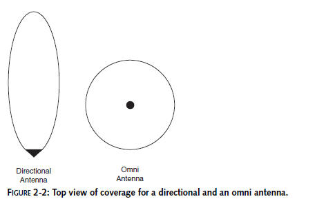
Figure 2-2 shows a diagram of two antennas viewed from
the top. The directional antenna is
most sensitive in one direction, meaning signals being sent and
received by the antenna will be strongest in the direction the
antenna is pointing. The omnidirectional antenna sends and
receives signals in all directions equally. This is a
generalization, but it’s mostly accurate. Later
chapters will delve further into the specifics of antenna
operation.
Since directional antennas direct their
information at a specific target (or at least in the direction
of the target), they require less power to transmit, but more
precision in their placement. Omnidirectional antennas need
little precision in their placement, but require more power to
send and receive signals. You are probably familiar with these
different types of antennas, because you see them almost every
day. A satellite dish would be considered highly directional,
looking up into space, while
the antenna on your car is omnidirectional,
listening to radio no matter which direction your car is facing.
Let’s take a closer look at these different types of antennas.
Omni Antennas
The omnidirectional antenna is probably the most
common Wi-Fi antenna available. Just about every Wi-Fi device
you can buy comes with an omni antenna. This is because the omni
is so easy to set up, and generally works in consumer
environments without much planning. There are a few different
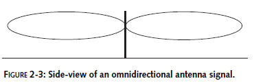
types of omni antennas. Omni signals spread out sideways, but
not vertically (see Figure 2-3).
Even though an omni antenna does not work very
well above and below, it is not considered a directional
antenna. Wi-Fi antennas are generally rated in two-dimensional
space that assumes it is mounted parallel to the Earth’s
surface. Knowing how the beam is shaped, and that an antenna is
not truly omnidirectional will help you choose the right antenna
for your Wi-Fi toys.
Dipole Antenna
The
dipole antenna is just about the simplest antenna
there is. The dipole is a half-wave antenna that consists of two
opposing radiating elements. It’s made up of two
quarter-wavelength poles
that are not connected to each other and fed in
the middle by the transmission line. A standard dipole is open
on each end, but it can also be folded over on itself. The
dipole you will build in this chapter is a folded dipole.
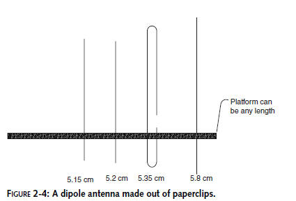
Figure 2-4 shows a simple dipole made from steel
paperclips. Each
arm of the
dipole is 31 mm in length, or 1/4
of a wavelength for Wi-Fi channel 6. The center conductor is
soldered to the right arm, while
the shield is soldered to the left arm. It doesn’t matter to
which side you solder. The dipole
antenna is unique in that it can be mounted vertically or
horizontally.When standing
vertically, the dipole antenna is omnidirectional.When
horizontal, this antenna will radiate
outward in two directions off the sides (and slightly
upwards), like turning a donut on its edge.
Coaxial Antenna
A coaxial is another common antenna used in
Wi-Fi. It’s used on most wireless access points you can buy. If
the access point has a stubby little antenna on it, chances are
it’s a
coaxial
antenna.
The coaxial antenna works in much the same way as a dipole
antenna. The construction is
slightly different though. The antenna feed comes up through the
bottom with a metal casing around
the shield-connected arm. Coaxial antennas are usually a total
of half a wavelength with each arm
being one quarter wavelength of the frequency.
The
antenna in Figure 2-5 is from a common access point with two
antennas. The plastic on one of the antennas is removed to show
you the actual antenna element. You can see that the
cable runs through the base of the antenna. The center
conductor extends to the top while the
shield is soldered to the metal cylinder that becomes the
base radiator.
Antennas
are not really affected by plastic, rubber, and other
nonconductors of electricity. When
determining antenna shape, you can sometimes get an idea from
the outer covering. However, you
will need to check the antenna specifications to be sure of the
design. Or build it yourself!

Vertical Driven Array Antenna
The
driven array antenna
is often used for mobile
applications. This is a vertical antenna with
gain created by multiple segments of half-wavelength
elements arranged vertically end-to-end
to achieve gain. An array is simply more than one element
working together. The driven array
means that each element has an electrical connection with the
one next to it. The signal is
driven into each radiating element via an antenna coil that
maximizes the transfer of energy
between adjacent elements.
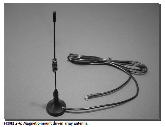
Figure 2-6 shows a magnetically mounted driven
array antenna with one quarter-wavelength element on the bottom
and one half-wavelenegth element on top separated by a coil. The
coil is used to match the antenna elements to each other. If an
antenna has a coil on it’s structure, it is most likely
separating antenna elements.
A driven array connects elements directly and electrically. A
parasitic array connects passively without a direct electrical
connection to the driven element.