Modifying Your Access Point with a High-Gain
Antenna
You
buy a wireless access point and a laptop card with visions of
working or surfing the net in the kitchen, in the bedroom, on
the deck, or in a hammock in the
backyard.No longer will you be chained to a desk or a
table! Only one problem:No matter where you place the
access point in your house, there
are significant areas where your laptop can’t maintain a
consistent connection and downloads
take forever when you do have a connection. In
other words, in technical terms, “coverage stinks.”
What do you do? One likely answer is to use a
high-gain antenna for the access point. A high-gain antenna
multiplies the access point’s range for both transmission and
reception. That is, it boosts both receiver sensitivity and
transmitter output. Increased signal strength means faster
transmissions, too, since most access points are configured to
drop back to a lower data rate when the quality of the
connection deteriorates. Although an indoor high-gain antenna
may cost about as much as the access point itself, (an outdoor
model would cost even more), it will be worth it if it makes the
difference between a pokey, limited, unreliable network and one
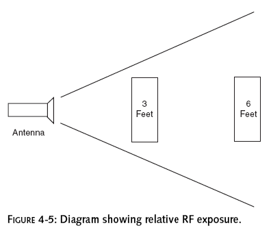
that is fast, far-reaching, and robust. A sample setup is shown
in Figure 4-1.
The mechanics of attaching the antenna can be
really easy, especially if you have a Linksys access point. You
do have to make sure that you get (or build) the right pigtail
cable for connecting the access point to the antenna cable. You
should also choose an antenna that will cover the intended area
while minimizing interference. Positioning and aiming the
antenna for best results can take a bit of experimentation, too.
You should be aware that it is possible to make
your Wi-Fi network
too
powerful. As
wireless networks extend their reach, they are more likely to
“jostle” one another. Your neighbors could start picking
up your signals, or you might start
picking up theirs. The FCC has rules to keep such interference
to reasonable levels. There are also FCC safety rules about how
much RF energy human beings should
be exposed to over how long a period of
time. By keeping interference and safety guidelines in
mind when you design your system, you’ll protect yourself and
others, and you’ll have the added
comfort of knowing that you’re legal.
 n
this chapter
n
this chapter
The chances of getting busted for going over the
limit for an indoor network are about the same as for removing
one of those little “do not remove on pain of death” tags on a
mattress. Basically, someone has to complain before the FCC does
anything. However, if you are counting on this system, say for
your business, it’s best to stay within the rules.
If you get decent performance when the access
point and the client are close, but things get flakier the
farther away you get, a high-gain antenna on the access point
could be just the thing to pump up your signal.
Here’s what you will need for this project:
1.
Wireless access point with an external antenna connector and
detachable antenna
2.
High-gain antenna
3.
Pigtail cable
4.
Antenna cable
5.
Hardware and tools (such as screws and screwdriver) for mounting
the antenna
6.
Opposable thumbs
See Chapter 1 for instructions on building the
antenna cable. In fact, even if you don’t want to make your own
antenna cable, Chapter 1 has good background information for
many of the topics in this chapter.
Although the 2.4 GHz technology is relatively
uniform worldwide, the rules about who can use it and how it can
be used vary from country to country. If you are located outside
the United States, manufacturers and governmental agencies may
be good sources of information on what is allowed in your
region.
Choosing an Antenna
There are two kinds of high-gain antennas:
omni
and
directional.
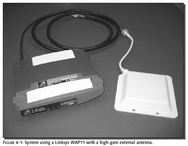
An omni antenna transmits and
receives in all directions, though usually more horizontally
than vertically: Its radiation
pattern looks like a doughnut, with the antenna at the doughnut
hole.
A directional antenna transmits and receives in
a narrow beam, usually within a 30 to 60 degree “slice” of a
full circle (see Figure 4-2.). You can envision its radiation
pattern as a spotlight. A directional antenna with a fairly
broad beam, such as 120 degrees, is called a “sector” antenna.
Chapter 5 has a section on
Picking the Right
Antenna that
provides some more information on this topic.
The focused beam of a directional antenna provides three
advantages: First, by focusing your beam, you get a more
powerful signal for the same transmission power. Second, you’re
less likely to cause or experience
interference problems, because you can aim your transmission
beam and focus your receptivity. Third, directional
antennas, due to their reduced potential for
interference, typically can have higher gain than omnis.
You should use a directional antenna if
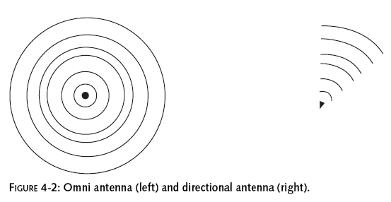
possible. If you need broader coverage than a highly
directional antenna can provide, you may
be able to compromise on a sector antenna, and put it in
one corner of the desired coverage
area. (See Figure 4-3.)
Staying Legal
FCC regulations specify three things:
Maximum permitted transmitter power output (TPO) of the radio in
the access point, before the signal
reaches the antenna Maximum permitted antenna gain without
requiring a reduction in TPO Required reduction in TPO for every
decibel (dB) of antenna gain above that maximum
For an introduction to decibels, see
Measuring Line Loss in
Decibels in
Chapter 1.We will introduce just
one unit of measurement here that wasn’t mentioned in Chapter 1:
dBi, decibels referenced to an
isotropic
radiator.
An isotropic radiator transmits equally in all
directions. The radiation pattern of a perfect isotropic antenna
would look like a beach ball, with the antenna in the center of
the ball. The term “isotropic” basically refers to an ideal omni
antenna.
For instance, since each 3 dB represents a doubling of
power, 6 dBi describes an omni antenna
that doubles power twice—that is, one that multiplies
power by a factor of four.
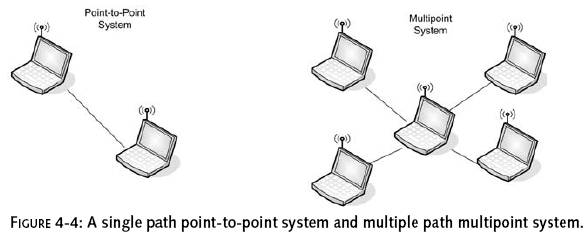
The FCC regulations do not talk in terms of omni
and directional antennas. Instead, they talk about
“point-to-multipoint” and “point-to-point” networks. Strictly
speaking, every network in which an access point is accessed by
clients is point-to-multipoint in its design. However, the
apparent intention of the regulations is to permit more gain for
more focused transmissions, because they are less likely to
cause interference. It is this intention which is followed in
common practice. Thus, omni antennas are treated as
point-to-multipoint, while directional antennas are treated as
point-to-point. Figure 4-4 shows a point-to-point versus
multipoint network.
In addition, the regulations state that each
specific antenna model must be certified with each specific
access point model, before they can legally be used together.
However, we are not aware of any effort to enforce this at the
end user level, and common practice seems to be: to stay within
certification guidelines, as opposed to actually certifying in
every case.
We are not attorneys. Our interpretation of FCC regulations and
practices is not authoritative. In fact, much of this is under
review by the FCC and industry. Regulations or legal definitions
may change any time.
FCC Point-to-Multipoint Rules
Here’s a summary of the FCC rules for
point-to-multipoint transmissions:
The
radio in the access point can have up to 30 dBm TPO. You can
have a 6 dBi antenna without reducing TPO. Assuming 30 dBm TPO,
that’s a 36 dBm signal from the
antenna. The TPO needs to be reduced 1 dB for every dB of
antenna gain over 6 dBi. (In other
words, for every step forward, you have to take one step
backward.)
30 dBm means you take 1 mW and double it ten
times (because 30 is 10–3, and 3 dB is a doubling). This works
out to a number that is so close to 1 W (1.024 W, to be exact)
that everyone just calls it 1 W. Because each 3 dB represents a
doubling of wattage, 6 dBi means the maximum permissible
transmitted signal from the antenna is 4 W Equivalent
Isotropically Radiated Power (EIRP). (1 W 2 2) The bottom line:
If you’re using an omni antenna, design your system so that it
doesn’t radiate more than 4 W EIRP.
The radio in the Linksys BEFW11S4 access point,
for instance, puts out 68–78 mW, depending on the channel. Even
assuming 100 mW TPO, a 9 dBi antenna would bring that up to just
800 mW EIRP. You’d have to go over 15 dBi before you might be in
danger of exceeding the 4 W EIRP limit (100 2
(15/3)
�
3200).With a 78 mW TPO, a
17 dBi antenna is still under the
limit (though just barely). (78 2(17/3)
�
3962)
You can look up the maximum output of your
access point radio on the FCC Web site, if you have the FCC ID
of the radio, which should be provided on the access point. For
instance, on our Linksys BEFW11S4, the FCC ID of the radio is
MXF-C901114. You can go to www.fcc.gov/oet/fccid/ and search on
the FCC ID. One place that TPO information should be listed is
under RF Exposure Info.
The omni antennas that come with access points
are generally 3 dBi or so. Therefore, anything much less than 6
dBi would be only marginally better than the manufacturer’s
antenna. Most of the add-on omni antennas on the market are in
the 6 to 15 dBi range, which is the sweet spot for equipment
like Linksys access points—safely legal yet definitely
worthwhile.
FCC Point-to-Point Rules
Point-to-point rules are the same as
point-to-multipoint rules, except that you need to reduce TPO 1
dB for every 3 dBi of antenna gain over 6 dBi. In other words,
three steps forward, one step backwards: A big improvement over
the corresponding point-to-multipoint rule! For example, a 24
dBi antenna is 18 dB over a 6 dBi antenna. So, to use a 24 dBi
antenna, you would have to lower a 1 W (30 dBm) radio 18/3 or 6
dB to 24 dBm or 1/4 W. (18 steps forward, 6 steps back.)
In practice, many access points don’t allow you
to adjust the TPO. However, you can take into account the fact
that the existing TPO of the access point is less than 1 W. For
instance, 125 mW is 9 dB less than 1 W. Therefore, we would be
very safe in using the 24 dBi antenna in the previous example
with our Linksys BEFW11S4, because its radio comes “pre-lowered”
more than the required 6 dBm.
Some wireless devices let you reduce TPO,
allowing you to use a more powerful antenna without increasing
EIRP. The main advantage of doing this is the increased receive
sensitivity of the more powerful antenna.
In fact, the rated Linksys TPO of 78 mW is actually about
11 dBm below 1 W. Therefore, if you
wanted to push the limits, you could use a 39 dBi antenna—33 dB
above 6 dBi—because 33 dB divided
by three is 11. (33 steps forward, 11 steps back.)
In practice, most of the available directional
antennas for Linksys access points are in the 12 to 27 dBi
range, keeping them within the intention of the FCC regulations.
FCC Safety Rules
The 2.4 GHz frequency band is used in microwave
ovens, because RF in this band tends to generate a lot of heat
when it hits something. This heat can be dangerous to the human
body. For this reason, the FCC has specified Maximum Permissible
Exposure (MPE) limits for 2.4 GHz signals. The FCC has also
issued a bulletin, OET Bulletin 65, “Evaluating Compliance with
FCC Specified Guidelines for Human Exposure to Radio Frequency
Radiation” that spells out the guidelines. (It’s at
http://ftp.fcc.gov/oet/info/documents/bulletins/#65.)
These guidelines deal with how much radiation
hits people, not how much the antenna puts out. As with a
microwave oven, the size of the heated body is also important.
Specifically, the FCC guideline states that potentially
hazardous exposures may occur at levels over 4 watts per
kilogram (4 W/kg) averaged over the entire body. Even continuous
exposure to 4 W/kg or less should be okay.
We’re not going to get into the mathematics of
calculating exposure levels. Also, we are not doctors, nor are
we dispensing medical advice. But we will note that the exposure
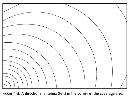
is inversely proportional to the square of the distance (double
the distance, one fourth the exposure). Therefore, the easy way
to minimize health hazards is to avoid spending extended periods
of time near high-gain antennas. Figure 4-5 shows the relative
exposure from someone standing 3 feet and 6 feet from the
antenna.We would not stay within two feet of an ordinary Linksys
access point with 3 dBi antennas for more than five minutes on a
regular basis. And we’d double the distance for each 6 dBi of
added antenna gain.