Building the Paperclip Antenna
Building the antenna is a seven-step process, as
follows:
1.
Prepare the antenna
elements
2.
Get the mounting platform
ready
3.
Create the driving element
or dipole
4.
Prepare the pigtail
5.
Attach the pigtail to your
new antenna
6.
Secure the pigtail
7.
Insert the last few
elements into the antenna
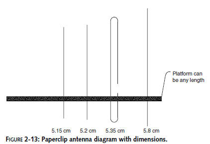
Figure 2-13 shows the basic components and how
they come together. Note that the rounded paperclip (piece 3) is
the actual driven element of the antenna. That is, it’s the wire
getting the radio signal from the wireless card. The other
paperclips (pieces 1, 2, and 4) shape the beam to make it more
directional.
Step 1: Preparing Your Wire Prongs
Each radio frequency has a specific
wavelength.To function as an antenna, the dipole loop has to be
half the length of that wavelength.
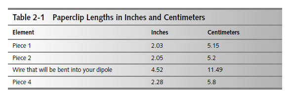
Take your needle-nosed pliers and carefully
straighten four large paper clips. Cut them to the lengths
indicated in Table 2-1.
Step 2: Preparing Your Antenna Platform
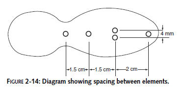
Carefully mark on the wooden platform the five
places where the wires of your antenna will be passing through.
See Figure 2-14 for hole spacing for the paperclips.
This
design is optimally tuned for reception on Wi-Fi Channel 6 (the
approximate middle of the frequency band). It will also work on
the other Wi-Fi channels. But if you really want to get peak
frequencies, paperclip length and distance apart from each other
will differ for each channel. See the section
How Are Dipole Dimensions
Calculated later in this chapter.
Using your hand drill, drill the five holes
using a drill bit slightly smaller than the paperclip wires.
As an alternative, you can punch the holes by
laying the platform flat on a table surface, and gently tapping
a thin wire brad through the wood with a hammer. However, you
can easily split the wood this way (especially on platform
materials like an ice cream spoon or a popsicle stick).
Patience is a virtue when mounting the
paperclips. Work the paperclip into the material slowly with a
gentle twisting and pressing force and everything should be
fine.
Step 3: Creating Your Dipole
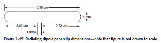
Take the longest wire (the one that is 4.52
inches long) and form it to match the template in Figure 2-15.
This template is printed to scale. After bending the paperclip
as described here, lay it on top of this diagram to ensure the
correct dimensions Take your needle-nosed pliers and make a line
on the nose at the point where it is 0.16 inches (4 mm) thick.
Clamp the largest wire with the pliers and make a bend that
starts 1.3 inches from one end,. Slowly wrap the paper clip wire
around the needle nose, creating a fishhook that is 0.16 inches
wide (4 mm).
Carefully press the longest end of the fishhook
through the first appropriate hole on your platform.Work the
wire into the hole, until the second end comes up to its
appropriate hole. Ease that second wire through so that its end
just pokes through on the other side of the platform.
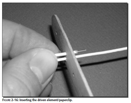
Take the long protruding end of the wire and
carefully create the second bent end, bringing the two ends
extremely close together (about 1 mm or 0.04 inches), and create
your radiating dipole. (See Figure 2-16.)
Step 4: Preparing the Pigtail for Attachment
Take your wire cutter and simply snip off the
large standard N connector on the end of the pigtail. This is
where a factory-built antenna would be connected to the pigtail
or jumper cable (as described in Chapter 1). Since we are
soldering the antenna directly to the pigtail, the connector is
not needed.
Be careful not to snip off the smaller end of
the pigtail, which needs to be attached to your laptop wireless
card.
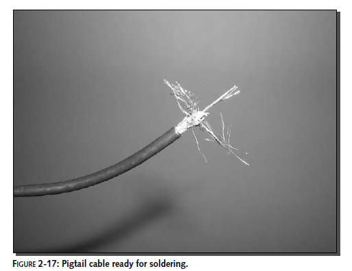
Strip off about three-fourths of the outer insulating
jacket and the inner dielectric insulation surrounding the core
conductor.
You will need about 1/4 inch of the central core
free, to create a soldered connection to one end of the dipole.
And you will twist about 3/4 inch of the outer shield into a
tight coil in order to solder it to the other end of the dipole.
(See Figure 2-17.)
Step 5: Soldering the Pigtail to the Dipole
Put the bent paperclip dipole in a stable grip,
either in a small tabletop vice, or in a pair of vise grips.
Don’t touch the paperclip or the solder iron while you work on
this, both will be very hot. Be sure to wear eye protection
because splattering solder can cause serious eye damage. Also,
the solder resin causes some fumes that can damage your lungs,
so make sure your workspace is ventilated to avoid any unhealthy
buildup of vapors.
Carefully solder the core conductor and the
shield to either end of the bent dipole radiator (as shown in
Figures 2-18 and 2-19).
Both sides of the paperclip need
to be soldered to the pigtail, but they must not touch each
other or the antenna will be useless. When you choose a mounting
platform, plan ahead to prevent the ends from touching.