Building a Solar-Powered Wireless Repeater
Imagine placing an access
point high up on a hilltop.What a view that
system would have! And now that you have an outdoor
wireless system on your roof, the
next question you will have is, “How do I extend the
reach of my network?”
A wireless repeater can be used to reach out
beyond the limits of your wired access point. By pulling energy
directly from the Sun with a solar panel, the system can be
located out as far as the eye can see.
Revolutionary advancements in harnessing the
Sun’s power to createenergy have flourished over the last
decade. Solar power is becoming an accepted and, in some
cases, required component in structural designs of the 21st
century.
While once only viewed as a novelty, solar power
is quickly becoming an integral part of powering human
requirements. A combination of improved efficiency coupled with
the proliferation of the technology has reduced cost and opened
entire new markets for this stable energy source.
It was only a matter of time before solar power
was harnessed to drive remote networking components. That time
has come and as you create the system described in this chapter
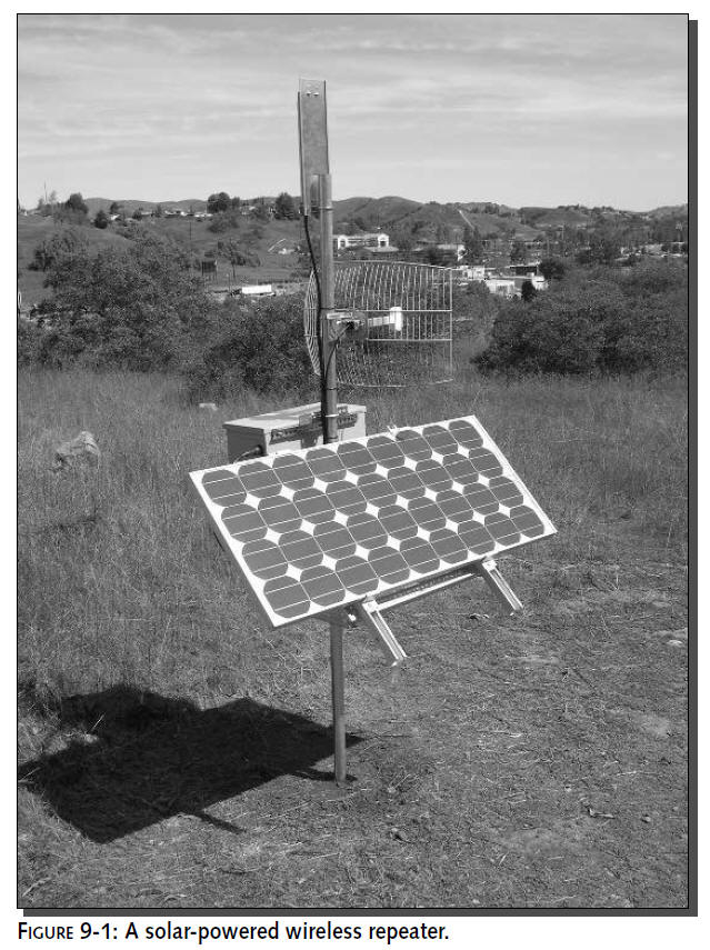
(see Figure 9-1), you will be a part of the energy revolution
and a friend to our fragile environment.
Implementing solar can be expensive. Yet, with
some creative sourcing and some do-it-yourself construction, a
solar repeater can be put together for less than you may think.
The items used in this chapter’s project are:
Solar Panel rated at 75 W, 12 V, 4.4 A
Two
wireless antennas, one each for downlink and end-user access
Antenna cables and pigtails
Two
wireless access points operating in Bridge mode
One
wireless access point operating in Access Point mode
Crossover network cable
Several feet of 10 AWG wire (black and red)
Two
35 ampere-hour (Ah) deep cycle lead-acid batteries
Solar system charge controller
DC-to-AC power inverter rated at 300 W or higher with a modified
sine wave output
AC
Power strip with no surge suppression circuitry
Galvanized steel outdoor enclosure rated for outdoor operation
(NEMA 3R) Water sealant tape
Adhesive Velcro tape, 2-inch width
Wiring tie downs (optional)
Flexible rubber conduit and end connectors
Galvanized steel angle-iron to construct the solar panel mount
2-inch diameter, 10-foot pole, and concrete
While solar power lends itself to limitless
possibilities, this chapter will focus on integrating a wireless
infrastructure. Once we’ve opened your eyes to the potential, we
encourage you to harness the Sun’s power to provide a reliable
and free source of power for your networking and computing
needs.
Learning Solar Basics
Photovoltaic
power generation systems
(also known as solar or PV) are made up of interconnected
components, each with a specific function. One of the
most attractive features of a PV system is its modularity. As
your requirements change, individual components can be added or
upgraded to provide increased capacity and flexibility.
Although your initial components will
vary depending on your application, PV systems generally
conform to these specific configurations
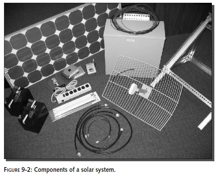
(see Figure 9-2):
Solar Array:
The solar array consists of one or more PV modules that will
convert sunlight into electric energy. The modules can be
connected in a series or parallel configuration
to provide the voltage and current requirements of your
application.Typically the array
will be mounted on a metal post or structure and tilted to face
the sun for maximum exposure.
Charge Controller:
Although charge controllers can be purchased with many options,
their main function is to maintain the batteries at the proper
charge level, and to protect them
from overcharging, which would damage or reduce life expectancy.
Battery Bank:
The battery bank contains one or more deep-cycle batteries,
connected in series or parallel
depending on the voltage and current requirements of the
application. The batteries store
the power produced by the solar array and discharge it when you
need it.
Inverter: An
inverter is required when you want to power AC devices directly
from the solar system. The inverter
converts the DC power from the solar array/batteries into AC
power.
AC and DC Loads:
These are the appliances or devices that consume the power that
you are generating with your solar
array.
Balance of System:
These components provide the interconnections and standard
safety features required for any
electrical power system. Included in this group are:
Switches
Fuses
Circuit Breakers
Meters
Cabling
Several new technologies are emerging, including
fuel cells and microturbines that can generate electric power in
a distributed fashion, that is, from locations close to the
end-user. However, solar electric power offers many unique
benefits apart from other distributed generation systems.
By crafting a successful solar application, you
can reap the benefits that come with using a renewable energy
source. As a direct result of improving technology and declining
PV prices, practical applications for solar cells have steadily
expanded from space missions to remote power and personal
electronic devices. Since the mid-1990s, PV has become a
practical source of solar electric generation in the $800
billion electric power industry.
Using solar power in your application creates a
highly available wireless network without the electrical
delivery costs. A system like the one you will build in this
chapter can run for years with little more maintenance than the
occasional “window cleaning” wipedown of the solar panel.
Setting Up a Wireless Repeater
Before getting in to powering a solar system,
you will need to determine where this repeating network node
will be located. Much of this information is covered in Chapters
8 and 13, so here we will briefly cover how to determine a
repeater site.
The concept of a wireless repeater is simple:
use a wireless backhaul to beam a signal to an access point that
is accessible by the client. Figure 9-3 shows how this would
work. The access point sits where client devices (i.e., a laptop
computer) could connect while the backhaul links the signal down
to the wired Internet.
A
backhaul is a
point-to-point network link created to maintain a connection
between a remote site and the
network base station. The wireless backhaul is meant to carry
network traffic from the repeater station down to the base
station. Traffic on the backhaul is generally only between the
two points. The wireless backhaul
has an uplink
(to the repeater) and
a downlink
(from the repeater).
The wireless repeater system consists of a total
of three Wi-Fi radios. One is set up as an access point that
your users will connect to via their laptop, PDA, or other
wireless device. The second radio is set up in a dedicated
bridge mode. The
bridge is used
to link directly to the network
base station, which is the third radio.
When configuring multiple radios in a single
location, as used in the repeater enclosure, it is a good idea
to select channels as far apart as possible, for example,
channels 1 and 11 in the United States. If both radios were on
the same channel you would get far too much interference, even
though the antennas are pointed in different directions. This
separation helps prevent signal overlapping because the radios
are physically so close together.

The system will require two antennas on the
repeater structure, one for the bridged backhaul, or downlink,
and one to link to wireless clients. Depending on distance and
interference issues, the bridge link would usually require a
highly directional antenna. The access point would need an
antenna suited to the coverage area.
This configuration requires three wireless
devices (not including the clients).Two devices operate in
bridge-mode, while one device acts as an access point. Of
course, this is just one configuration of many. It’s conceivable
that a wireless signal could be repeated over and over.
Although, in practice, a large number of repeaters cause
processing time delays that could create synchronization
problems with traditional Internet protocols.
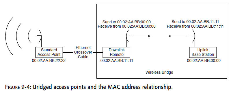
A wireless bridge is where two wireless devices
are configured to allow connections only to each other. This is
usually done by entering the MAC address of each access point
into the other access point. See Figure 9-4 for an example.
Access points in bridge mode will only accept traffic from the
other end of the bridge.
Before getting into the solar installation,
configure the wireless equipment in a lab setting. Youwill need
to configure the bridges individually, and the access point
should also be configured at this point. The wireless radios
used in this chapter are basic off-the-shelf D-Link access
points. These are not necessarily what you would want to run in
this type of situation. Considering the money, time, and effort
of integrating a solar system, extra cost on the wireless radio
components can be justified. These radios can vary widely. Any
wireless hardware can be used for the repeater section.
Refer to Chapters 8 and 10 for examples of hardware used for
providing wireless Internet access.
The D-Link product is one of the few on the
market with a built-in repeater mode. This repeater mode can
function well in some environments. However, a single-radio
repeater has less than 50 percent of its bandwidth available due
to the simultaneous uplink and downlink. Also, the D-Link
product does not work well with two antennas. Indeed, the recent
version has only a single antenna connection. Optimally, two
radios are needed for a 100 percent 802.11b bandwidth repeater.
The key to a wireless repeater is the bridge.
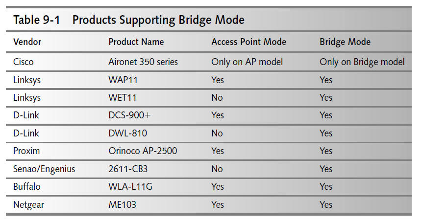
Some products that support bridging are listed in Table 9-1.
These products should have documentation available with details
for bridge configuration. Please refer to the documentation of
your specific equipment for details.
Integrating Solar Power
Aside from the obvious free source of power,
there are several other benefits to “solarizing” this leg of
your network infrastructure. First and foremost, having an
un-tethered wireless access point will enable great flexibility
in how and where you get network services within the local
region.
Hilltops are no longer out of the equation. By
placing a node on a remote hilltop, line-of-sight and
interference issues can be minimal. Additionally, a solar
repeater mounted to a tower would have a commanding view over a
low undulating landscape like farmlands, desert, or wilderness
areas.
Understanding Solar Modules
For this application, a 70-watt PV system will
be sufficiently adequate. This system will be preconfigured to
12 V and produce 4.7 A.We recommend using a PV module with a
glass surface that is impact-resistant and allows maximum light
transmission.
Choose a single crystalline solar cell,
encapsulated and bonded to the glass in multiple layers of
ethylene vinyl acetate (EVA) and laminated with a backing to
insure long life in severe conditions. The Shell Solar model
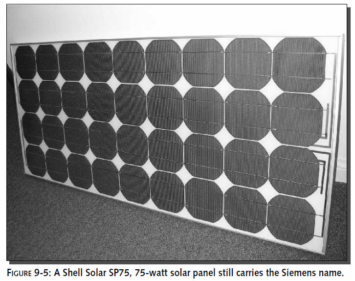
SP75, 75-watt solar module fits the bill nicely.
The model we are using (a Shell Solar SP75, see Figure
9-5), uses a proprietary technology
(CIS Thin Film Technology) to efficiently create electricity
from the sunlight. This module is
designed for use in 12 V systems. This system’s ability to
deliver battery-charge power in
low-light situations makes it particularly
effective for specialized applications and in adverse or
changeable environments.
Siemens solar division was acquired by Shell in
early 2002. Shell (now Shell Solar) did not begin renaming the
Siemens product line until mid-2003. You will still find
products carrying the Siemens name. The Siemens branded products
will eventually disappear from the marketplace as new products
are developed.
These panels are engineered and manufactured for
durability and ease-of-use. They are fully framed in anodized
aluminum with pre-drilled, strategically positioned mounting
holes to ensure secure and easy installations. A clamp-type
mounting system can be used, so no drilling is required.
You will also want to use a weather-resistant
junction box mounted to the solar module that will accommodate
all wiring. It should include moisture-tight strain relief
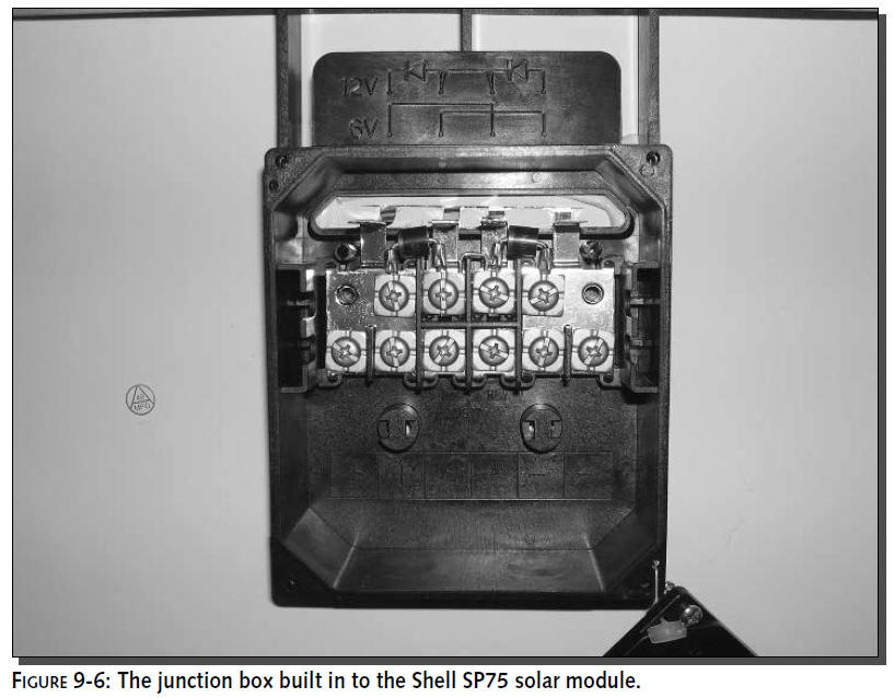
connectors, electrical conduit, and a bypass diode. Figure 9-6
shows the junction box on the SP75. Notice the jumpers and
bypass diode. These components connect the panel junction in
such a way as to provide 12 V. This particular solar module can
also be configured for 6 V operation.
Solar Power Specifications
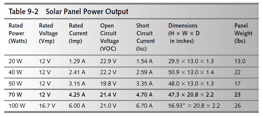
Output values of various solar modules are shown
in Table 9-2. This is an approximation based on several
manufacturers’ claims for power productivity. Your results may
vary depending on
the physical location of your solar system and
the availability of consistent sunlight exposure. The row in
bold is an optimal choice for the project in this chapter. More
power will charge batteries faster, keeping them topped up for
cloudy days.Too little power may cause a power outage from
drained batteries due to decreased charge capacity.
Solar power ratings assume operation at a
Maximum Power Point (MPP), which is generally considered
impossible to achieve in real-world deployments. Panel output
will vary based on factors such as temperature, panel tilt
angle, atmospheric conditions, and even cleanliness. Expect
output power somewhere in the 80 to 90 percent efficiency range
during peak hours of sunlight.
Finding PV sources
There are many high-quality products that are
suitable for this application. Now that you have established
your baseline requirements, we will recommend a couple of
options that you can choose from. Of course we have our favorite
based on optimal output, quality of construction, and quality
service from the vendors, but based on your geographic location;
you may need to find options that will meet both your cost
requirements as well as time constraints.
PV panels are a somewhat specialized product and
generally cannot be picked up at the local retailer. However,
some electronics stores can special order solar panels designed
for RV battery backup power. Largely due to the demands of
retail distribution and availability, systems available at local
stores can costs hundreds more than a solar module from a
distributor or local solar specialist.
Since your wireless repeater system is
relatively small and specialized, you may be able to find a
local solar specialist with spare 75-watt panels lying around.We
found this one from a residential system installer that was
using panels like this for decorations around the office. Buying
a solar panel from extra inventory can reduce the price
considerably.
Popular models include:
Shell Solar SP75
BP
Solar BPSX-70U
Both of these products provided all the features
and requirements outlined above. Either choice will result in a
successful exercise and provide years of high-quality power to
your system. This is not meant to preclude other quality
products, but to use as a baseline for you to look at and
compare with.
Solar power is obviously based on sunshine.
Solar providers will know a lot about your local sunlight
coverage. That is, incoming solar radiation or “insolation” will
vary from place to place on the globe. Talk to a local solar
specialist about hours of sunlight for your area. Maps and
figures are also available online. One such resource is provided
by Solar4Power at
www.solar4power.com/solar-power-global-maps.html.
The global map they’ve posted
online shows insolation values for every part of the globe.