Directional Antennas
You will build a directional antenna in this
chapter. A directional antenna increases gain in one direction.
By becoming sensitive in a single direction, the directional
antenna is a good choice for setting up links between distant
objects with a known location. Directional antennas are well
suited for the corner of a room, side of a building, or in a
hand-held mobile environment.
Directional antennas generally only work well in
one direction. The design of the antenna determines the field of
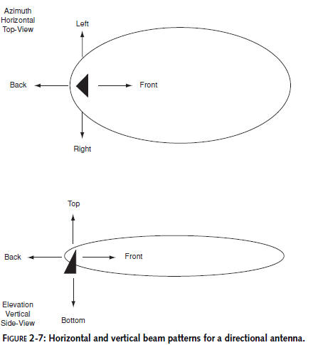
view, or beam pattern, for the antenna. Antenna beam width is
measured in degrees of a circle, as viewed from the top or the
side. The top view is measured as vertical beam width. The side
view is measured as horizontal beam elevation. Figure 2-7 shows
these measurements for a directional antenna.
Directional antennas are very helpful in
pinpointing a signal location, or for establishing a
longdistance link. The antenna you build in this chapter and in
Chapter 3 will help you later in the book.
Yagi Antenna
A
Yagi antenna
is a highly directional
parasitic array antenna. The shaping elements are not
electrically connected to the driven element. The Yagi
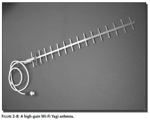
basically consists of a driven element, a
reflector, and two or more directional elements. Figure
2-8 shows a common Yagi antenna with
14 directional elements and one reflector.
In a very basic sense, the radiating element of
the Yagi is the only part that actually receives a signal. The
other components bend and shape the pattern of RF energy for
that single element. It works something like this: A transmitted
signal comes up the cable and leaves the driven element. It hits
the reflector and bounces toward the front of the antenna. Each
directional element then carries that signal further while
making it stronger.When the signal leaves the last element of
the antenna, it’s focused in a single direction. The reverse is
true for signals being received by the antenna.
The antenna you will build in this chapter is a
Yagi antenna. There is a driven element, a reflector, and two
directional elements.While the Yagi in Figure 2-8 uses aluminum
and fiberglass, you will construct yours of steel and wood.
Parabolic Antenna
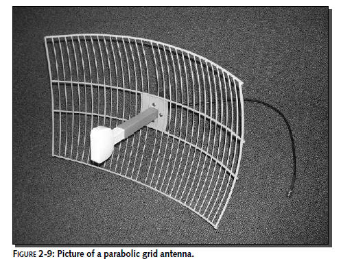
A parabolic antenna is very intuitive when you
see one, like the one shown in Figure 2-9. The rear portion of
the antenna is a curved reflector that bounces incoming signals
into the focal point of the curve. A small antenna is placed at
the focal point and becomes the
antenna feed
point.
The feed point usually has a half-wave dipole or other basic
antenna. For transmitted signals,
the reverse is true as signals bounce off the reflector out into
the distance.
Parabolic antennas have very high gain and are
very directional. They are most often used for direct links from
one station to another.When deploying a parabolic antenna you
need precise physical aim.
Panel Antenna
A panel
antenna is an array of rectangular flattened dipole
antennas arranged in a pattern on a panel. These flattened
dipole antennas are sometimes called
patch antennas.
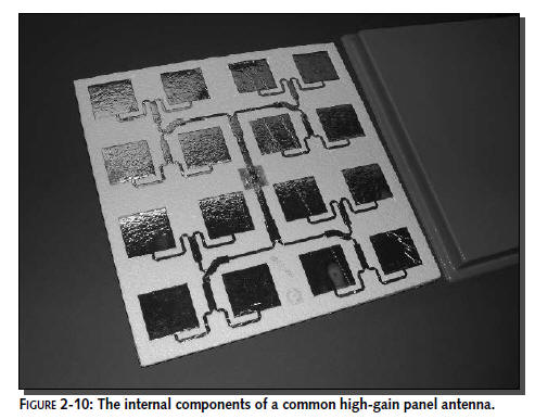
Because the patches are laid out in an array, the shape of the
radiation pattern is aligned and focused in one direction. The
more patches in the array, the more focused the antennna and the
higher the gain. Figure 2-10 shows the inside array of a very
high-gain panel antenna.
Panel antennas work well in one direction off
the face of the antenna. The metal backing surface is employed
as a reflector and mounting point for the panel antenna. The
face of the antenna is often covered in nonconducting plastic
for weather proofing and to help prevent damage.
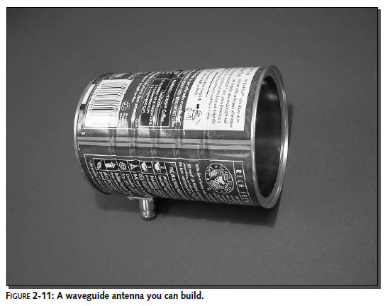
Waveguide Antenna
A
waveguide antenna is very strange indeed. This type
of antenna is actually formed by the space and the surface
surrounding an electrically conductive enclosure. The size and
shape of the waveguide determines the frequency at which the
waveguide will operate best. A small driven element in a precise
location near the rear of the waveguide creates the signal that
is shaped by the metal surface of the enclosure. The shape of
the enclosure directs the beam pattern outward, away from the
opening. Figure 2-11 shows a basic homemade waveguide antenna
made from a tin can. Waveguide antennas are often built from
aluminum. However, a tin can is a very good conductor, and it’s
the perfect size and shape for the waveguide antenna you will
build in Chapter 3.
Understanding Antenna Polarization
Antenna polarization stems from how an antenna
radiates energy. The design of an antenna forces certain
physical and electrical characteristics. As radio frequency (RF)
energy is shaped and radiated by the antenna, the antenna
changes the shape and beam pattern of the RF. Antennas are
usually designated with vertical or horizontal polarization. At
this point, the important thing for you to know is that
polarizations like each other. For example, a vertically
polarized antenna will work best receiving signals from another
vertically polarized antenna (vertical-to-vertical). In fact,
the signal strength can be 100 times less if you use mismatched
polarization (vertical-to-horizontal). You can use mismatched
polarization to your advantage when working with closely placed
antennas. The solar-powered repeater you will buld in Chapter 9
uses two antennas mounted on the same pole.To help keep them
from interefering with one another, they are placed in opposing
polarizations (horizontal and vertical). The end-result of all
this polarization talk is that you will want to hold your
antenna vertically upright (vertically polarized) to pick up a
typical store-bought access point (which is also vertically
polarized).When we say “vertical” we mean that the paperclips
are sticking straight up and down. “Horizontal” is when it is
flat as compared to the ground.