Understanding Coaxial Cables
Coaxial cables (commonly called
coax)
are used as the transmission line in a Wi-Fi system.
There are probably instances of Wi-Fi systems using a
different transmission line, but the most
common is coax.
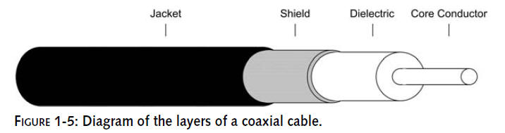
A coax cable is built in layers of the following
materials (see Figure 1-5):
Core: A center
of electrically conducting material like copper (solid or
stranded)
Dielectric: A
nonconducting material surrounding the core
Shield: An
outer layer of conducting material like steel (solid and/or
stranded)
Jacket: A
nonconducting protective surface like rubber or plastic
The RF signal is created or received and then
placed (or
injected) onto
the core of the cable. In theory, the signal is meant to travel
along the core of the cable, while the shield prevents the
signal from emanating outside the cable. In reality, some
signal is radiated outside the cable,
while electrical resistance in the cable reduces the
signal within the cable.
Coax cables come in two flavors when used with
Wi-Fi:
Coax jumper
Coax pigtail
A
coax jumper
is a larger diameter cable with low loss, meant for runs between
larger diameter connectors. A
common use of a jumper would be from a wireless access point
antenna jack directly to an antenna.
A
coax pigtail
is used as an interface
between larger diameter cables and the very small connectors
commonly used on PC cards. A common use of a pigtail
would be to connect a PC card to a coax jumper to an antenna.
Constructing pigtails takes much skill and
patience in soldering the tiny connectors to the small diameter
cable necessary for PC card connectors. For best results,
purchasing a preconfigured pigtail is the way to go. Selecting a
pigtail is covered in detail later in the chapter.
What Sizes of Coax Are Available
Cables come in many forms from different
manufacturers.We have found the optimum cable for ease-of-use
and low-loss performance is the LMR-400 cable from Times
Microwave. This cable has become the popular choice in building
wireless networks.
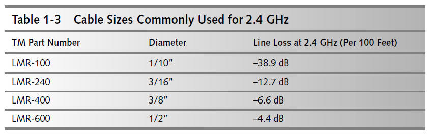
Table 1-3 shows various cable sizes from Time
Microwave. These represent the most commonly available cables
for use with 2.4 GHz Wi-Fi gear. The larger diameter cables are
harder to work with than the smaller cable because of their
rigidity and bulkiness. However, the larger cables have lower
signal loss. It’s a trade-off between ease of use, performance,
and cost. LMR- 400 is a good balance and costs about half the
price of LMR-600.
Keep It Short!
As shown in Table 1-3, cable loss is measured by
distance. Therefore, to keep the strongest signal and the lowest
loss, you should keep the cable as short as possible. For most
of the projects in this book, you will need cables of less than
10 feet in length. For larger projects, such as creating a free
wireless hotspot, you would need a longer cable.
Also, the cable type is very important at high
frequencies. For example, using 10 feet of LMR-100 cable induces
a loss of 3.9 dB, while the same length of LMR-400 induces a
tiny loss of 0.7 dB. Because of the high loss factor of LMR-100,
an access point should have no more than 3 feet of LMR-100 cable
between it and the antenna. On the other hand, an access point
using the more efficient LMR-400 cable could have a 20 foot–long
cable and work just as well.
Manufacturers list cable line loss as measured in 100
feet of cable. This does not mean you should, or even can, use
100 feet in your cable runs. You usually want as strong a signal
as possible coming out of the other
end of the cable, so either keep it short or use a larger
diameter cable.
Many radio enthusiasts and some manufacturers
host line loss or attenuation calculators on the Web. Search the
Web for
coax line
loss to find some
of these simple-to-use calculators.
Measuring Line Loss in Decibels
The concept of
decibel
measurement, or dB, is
covered more in Chapter 2. But for now, it’s easy
to think of it as the higher the number, the stronger the
signal. Remember that negative numbers
descend as they get higher (�80
is less than �30).Transmission
line loss is represented as
negative dB.
Wi-Fi radio transceiver effectiveness is
described as a measurement of power output and receive
sensitivity. Generally, these two measurements are expressed as
power in
milliwatts
(expressed as mW, meaning 1/1000 of
a watt) or as “dBm” (decibels related to 1 mW).
Decibel measurement can be confusing. But there
are two key concepts to make this easy to understand:
Decibels are relationship-oriented
Decibels double by threes
Relationship-oriented means that there is no set
value for a dB. The trailing letter in a dB measurement defines
the relationship. For example, dBm means decibels related to 1
mW of power. 1 dBm equals 1 mW.When you know the value of the
relationship, decibels are easy to calculate.
Doubling by threes is due to the logarithmic
nature of RF energy.When comparing a signal of 1 dBm (1 mW) to a
signal of 3 dBm (2 mW) you see that it’s double the power. This
doubling nature of power measurement or line loss makes it easy
to see how a cable can quickly reduce the RF signal to almost
nothing.
Calculating Line Loss
Continuing the last example (LMR-100 versus
LMR-400), let’s start with a signal of 100 mW (
�20
dBm) and send it out along the 100 foot–cable, as shown in Table
1-3. Start with the transmit power,
�20
dBm or 100 mW, subtract the negative dB of line loss, and
the result is the power at the other end of the cable:
1.
LMR-100 (38.9 dB loss):
�20
dBm�38.9
dB �18.9
dBm (about 0.001 mW)
2.
LMR-400 (6.6 dB loss):
�20
dBm�6.6
dB �13.4
dBm (about 20 mW)
In each case, it’s a large drop. But look at the
difference! LMR-100 drops power to a tiny fraction of the
original signal. LMR-400, on the other hand, while inefficient,
still has a usable signal. With either cable, once the signal
gets to the antenna and out into the air, there will be even
more signal loss. (See Chapter 13 for more on airspace loss and
link budget.) The significant loss in the cable makes repetition
important: keep it short!
Cable usually comes in bulk on reels of 500
feet. Bulk cable vendors will happily cut a length of cable for
your order. When ordering bulk cable, select a length of cable
that is several feet longer than required. Although it adds a
few extra dollars to the order, the extra cable makes it easy to
repair construction mistakes or connector problems.
Types of Coax Connectors
Connectors, obviously, are used to connect RF
components together. In Wi-Fi there are only a few common
connectors for large diameter coax. Unfortunately, the connector
styles are not commonly used outside of the Wi-Fi arena. So,
picking up a connector at your local consumer electronics store
is generally out of the question. Hopefully in the future, more
specialized retail establishments will carry this type of
equipment. But for now, expect to buy online or purchase
directly from distributors.
Male versus Female Coax Style
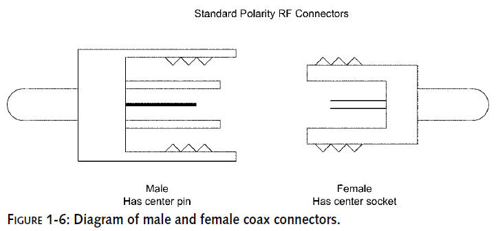
Connectors are designated as male and female,
which is another way of describing them as plug and socket. A
male coax connector has a solid center pin or plug with an outer
casing that enshrouds the female connector (see Figure 1-6). A
female coax connector has an open center socket which accepts
the male center pin.
In Wi-Fi coax cables there are often other
components to the cable connectors, such as the inner ring on a
Male N-type connector. The male/female designation is defined by
the center conductor (plug or socket).
Reverse Polarity
Reverse polarity
is another way of saying
that a connector has gone from plug to socket or
socket to plug, reversing its polarity. This adds
confusion to the entire male/female designation.
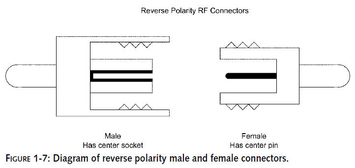
When using reverse polarity connectors, male and female
is reversed, where a male connector is
the same design except that its center conductor is a
socket. Female reverse polarity connectors
use a plug for the center conductor.
The outer casing is generally the same for
normal and reverse polarity. The RP style only changes the
center conductor. So a male RP connector still enshrouds the
female connector. See Figure 1-7 for a diagram of reverse
polarity connectors. Hopefully that will make it a bit less
confusing.
Reverse polarity is a commonly used connector
type in Wi-Fi devices. The style is not commonly used in other
coax applications. The general understanding regarding reverse
polarity connectors is that it fulfills government requirements
to make it more difficult for the average consumer to modify
Wi-Fi devices.Now that you know the secret, you’re not an
average consumer.