Step 7: Clipping the Core
Clip off the center core to the proper length
for the connector being used. The connector packaging or data
sheet should have this specific measurement. In the case of this
connector, we clipped it to 3/16 of an inch. If the center
conductor is too short or too long, the connector shell will not
seat correctly. Figure 1-18 shows the relative length for an
N-Male connector. After trimming back the core, remove any
ridges or burrs around the cut edge. This will allow the pin to
seat properly.
Step 8: Inserting the Center Pin
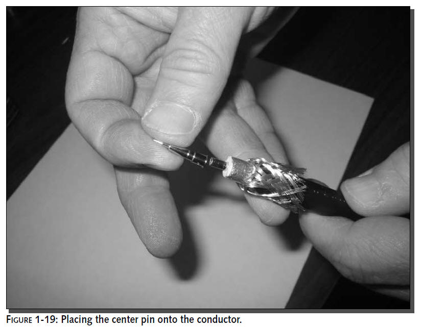
Place the center pin onto the conductor as shown
in Figure 1-19. Ensure the center conductor bottoms out at the
first stop of the pin. Also, ensure the pin rests within 1–2 mm
of the foam dielectric.
Step 9. Crimping the Core
This is the first of two crimps for the
connector. Ensure your crimp tool has the correct die for the
type of cable and connector being used. For LMR-400, the crimp
tool should have a die with hex sizes of 0.429 for the outer
ring, and 0.128 and 0.100 for the center pins.
The center pin for an N-Male connector is
crimped using size 0.128.
When you crimp coax cables, press all the way down once
only. The hex design of the crimp tool
die ensures the pin will grip the core properly in six
places. If another crimp is applied to “make
it tighter,” it could misshape the pin.
Place the pin into the crimp tool as shown in
Figure 1-20. The bottom edge of the pin usually will have a
small ridge to help line it up and keep the pin seated on the
core. Crimp down with even, strong pressure. If your crimp tool
has the ratcheting feature, it will apply only the necessary
amount of pressure before releasing.
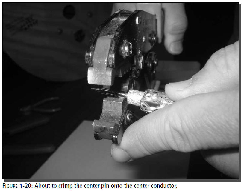
Figure 1-21 shows a properly crimped center pin.
Notice the marking around the edges where the crimp actually
clamped the pin to the center conductor.
Step 10: Placing the Connector Body
It’s time to place the connector body over the
pin. Figure 1-21 shows the connector about to slide onto the
pin. Before continuing, be very sure that the crimp ring from
Step 2 is still waiting for you down the cable behind the
splayed out shield before you place the connector body onto the
cable.
Ensure the crimp ring is on the cable before
snapping the connector shell into place. Once the shell is
snapped into place, it will be difficult to remove. Also,
removing and replacing the shell would degrade the cable
performance. If the ring is not in place, you’ll need to cut the
connector off and rebuild the cable with a new connector.
Line up the connector, and begin to slide the
connector over the pin, over the dielectric foam, and butt it up
against the shield strands. If all goes well, there may be an
audible click when the
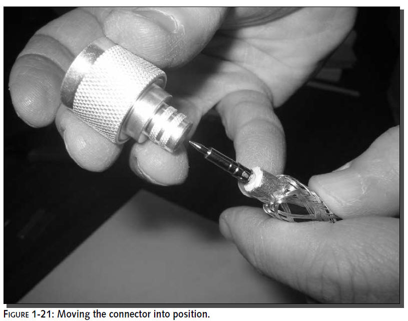
connector mates with the pin. This mating is
meant to hold the connector on the pin until the last crimp. Tug
lightly at the connector like you are going to pull it back off.
It should stay in place under light pressure. If forced or
yanked, it may come off, so be gentle.
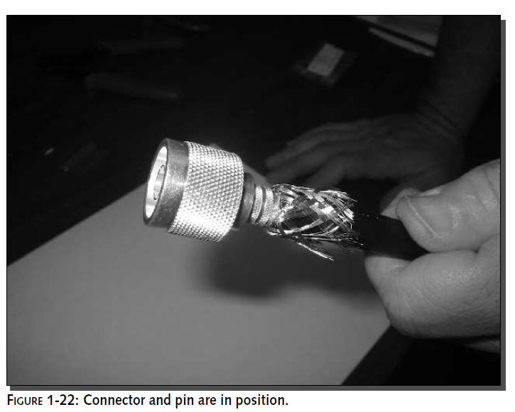
Figure 1-22 shows the connector fully inserted
with the shield still pulled back. Notice that the center pin
does not extend past the inner ring of the connector.
Step 11: Shields Up!
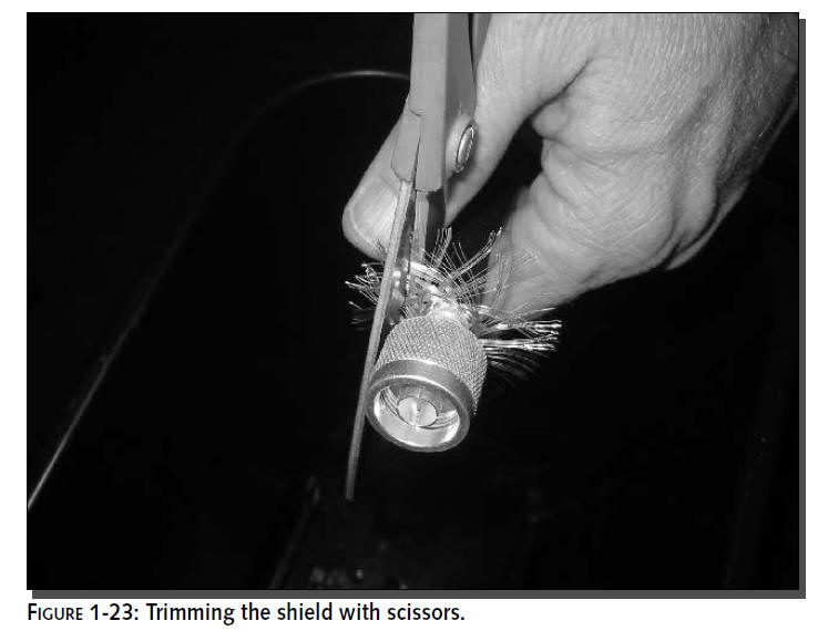
Fan out the shield strands and trim down with
scissors, as shown in Figure 1-23.To help cleanup, hold the
cable over a wastebasket. The goal is to trim down the shield
but still have enough to fit under the crimp ring.Trim the
shield down to about a quarter of an inch.
Shield strands are made of steel. The thin wires
can pierce the skin like a needle in some circumstances. Make
sure to handle the waste strands with care, and clean up the
area to minimize the chance of accidents.
Step 12: Placing the Crimp Ring
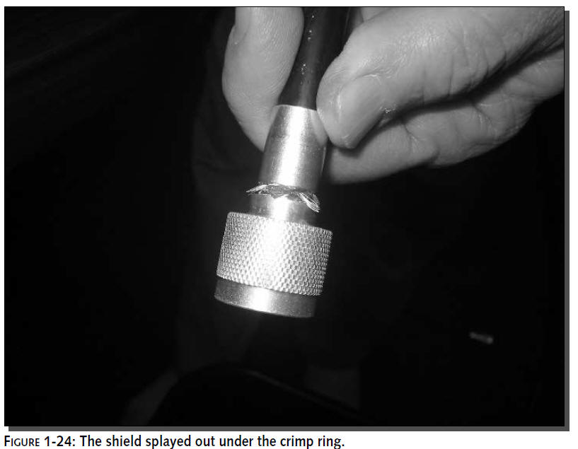
Now pull up the crimp ring you placed in Step 2.
The shield will slip under the crimp ring and should be splayed
out evenly around the connector body, as shown in Figure 1-24.
If the shield is still too long, move the crimp ring out of the
way and trim a little more of the shield with the scissors.Try
to get just enough shield under the crimp ring, but not sticking
out past the ring.
Step 13: Crimping the Ring
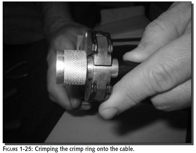
Finally, it’s time to crimp the crimp ring onto
the cable. This is the second of the two crimps needed to make
the cable. As in Step 9, use the crimping tool. But this time
crimp with the larger diameter hex size of 0.429. Place the tool
at the upper edge of the crimp ring, butted against the
connector body as shown in Figure 1-25. Crimp with strong, even
pressure, and only crimp once, just like in Step 9.
Step 14: Inspecting the Finished Product
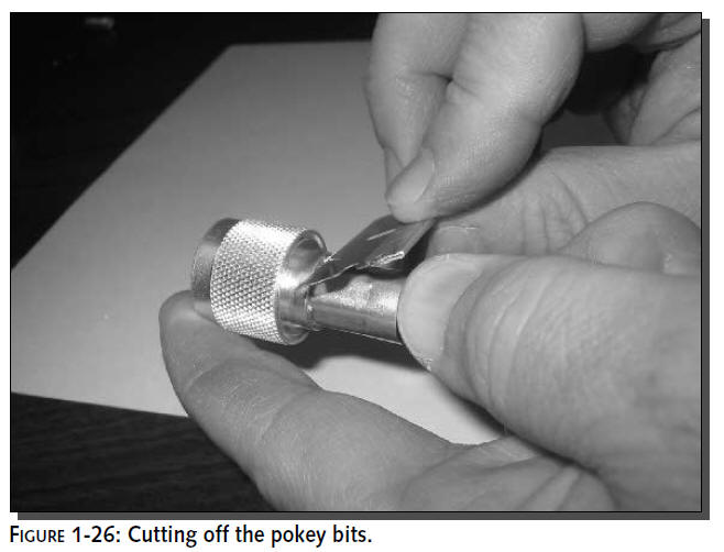
Now that the cable is complete, it’s time for a
visual inspection. Check the back of the connector at the seam
of the crimp ring. If there are any shield strands sticking out,
cut them off with the razor blade, as shown in Figure 1-26.
Clipping off the loose strands at the back of
the connector reduces the chance of injury when you’re screwing
on the cable. Loose strands are like splinters that may pierce
the skin of unwary fingers.
Visually check the front of the connector for any loose
bits of metal that may have dropped
into the connector during construction. If you find any, remove
them to prevent shorts.
That’s it! Now repeat steps 1 to 12 for the
other end of the cable. After doing a few of these, it will
become second nature.With practice, building a cable connector
can take just a few minutes.