Building a Coaxial Cable
That’s enough theory! Now it’s time to get your
hands dirty and get started on this chapter’s project, which is
building a coax antenna cable. Cable construction opens new
freedom to creating wireless projects.With this skill, you can
order the components you need and custom-build a cable that fits
your application perfectly.
And the cost of the components is usually lower
than buying a pre-built cable. N-Male is the most commonly used
connector for Wi-Fi cabling, because most antennas have N-Female
connectors. And, as you know, N-Male mates to N-Female. So,
these steps will assume you have chosen LMR-400 cable with the
standard N-Male connector. Please adapt the steps to your
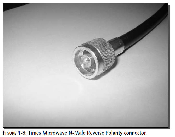
application where needed. Figure 1-8 shows the necessary
dimensions for a Times Microwave N-Male connector.
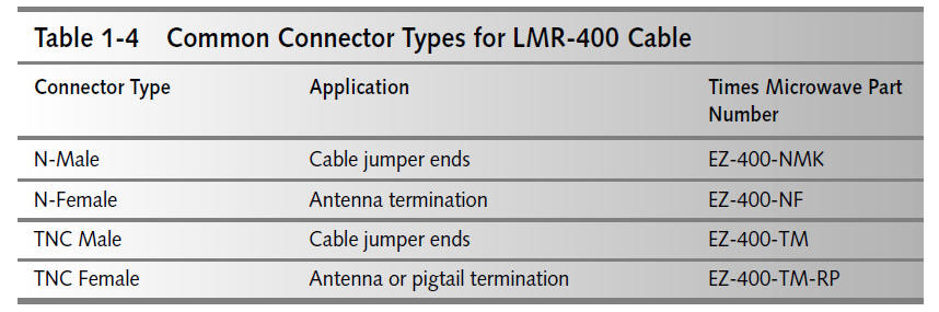
Table 1-4 shows a list of connectors for use
with LMR-400 cable. These connectors are solderless and each
requires only two crimps. The connector types listed here are
for hand-tightening. A myriad of other connector types are also
available. With the right set of tools, building a cable is a
step-by-step process:
1.
Prepare the cable
2.
Slide the crimp ring onto
the cable
3.
Strip off the outer jacket
4.
Pull back the inner shield
5.
Strip the
dielectric foam core
6.
Remove any shorting
material on the foam core
7.
Cut the center conductor
to correct size
8.
Place the center pin onto
the center conductor
9.
Crimp the center pin
10.
Place the connecter body
onto the cable
11.
Replace shield over the
connector body
12.
Place the crimp ring over
the shield and connector body
13.
Crimp the crimp ring
14.
Inspect
your finished product
There are a lot of steps, but it’s actually very
simple. Each step is discussed in detail in the paragraphs that
follow.
Step 1: Preparing the Cable
The cable is treated as a bulk item until ready
to assemble the end connectors. So the ends are often cut into
an irregular shape.
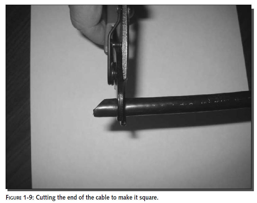
Use the cable cutters to square off the end of
the cable, as shown in Figure 1-9.
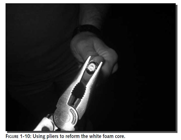
After cutting the cable, the dielectric foam
will become elongated. Use a set of pliers to reform the foam
into a rounded shape, as shown in Figure 1-10. This will make it
easier to strip later. Don’t worry about the shape of the shield
and outer jacket.
Step 2: Placing the Crimp Ring
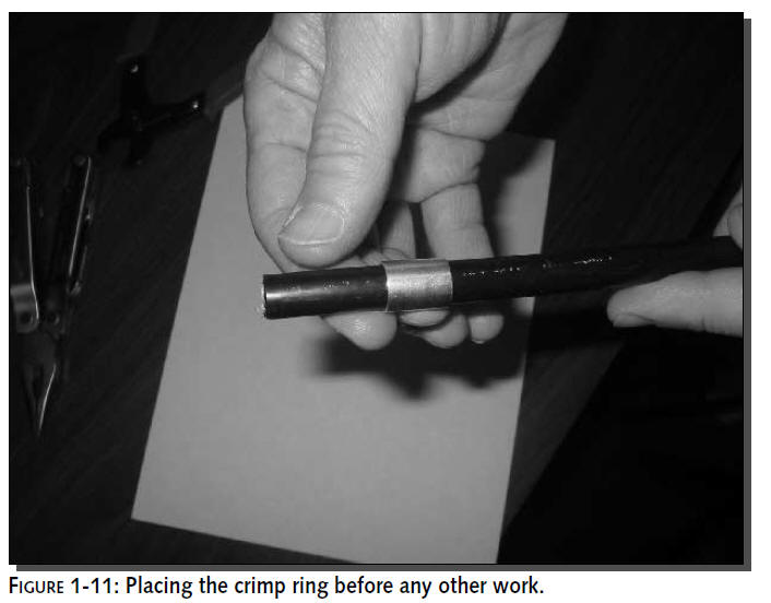
Before going any further, place the crimp ring
onto the cable as shown in Figure 1-11. Slide it out of the way
down the length of the cable. Later, you’ll pull the crimp ring
into place on the back of the connector shell.
Step 3: Stripping and Removing the Outer Jacket
There are special tools for stripping all types
of cables, but a razor blade works well, costs less, and is more
versatile. If you are very good at handling sharp objects, a
pocket knife works too. Check the instructions that came with
the connector for exact dimensions needed. Strip off about 1/2
inch more than necessary to leave room for trimming.
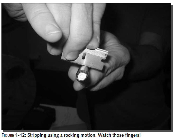
When stripping a cable with a razor blade or sharp knife,
try not to nick the underlying elements
of the cable. By rocking the razor blade, you will score
through the jacket without harming the
shield underneath.
Figure 1-12 shows a cut taking place around the
entire circumference of the cable. It’s a little unclear at this
angle, but my fingers are being kept well out of the way! Cut
through the outer jacket just enough to be able to pull away the
jacket without harming the shield.
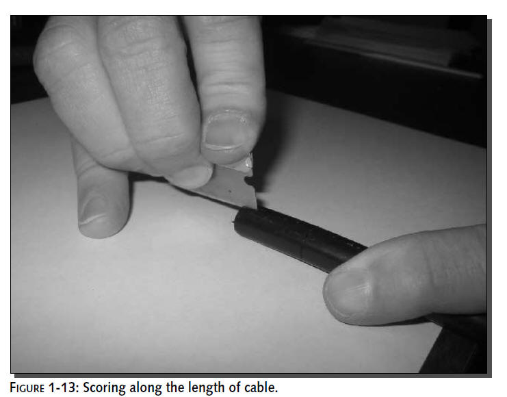
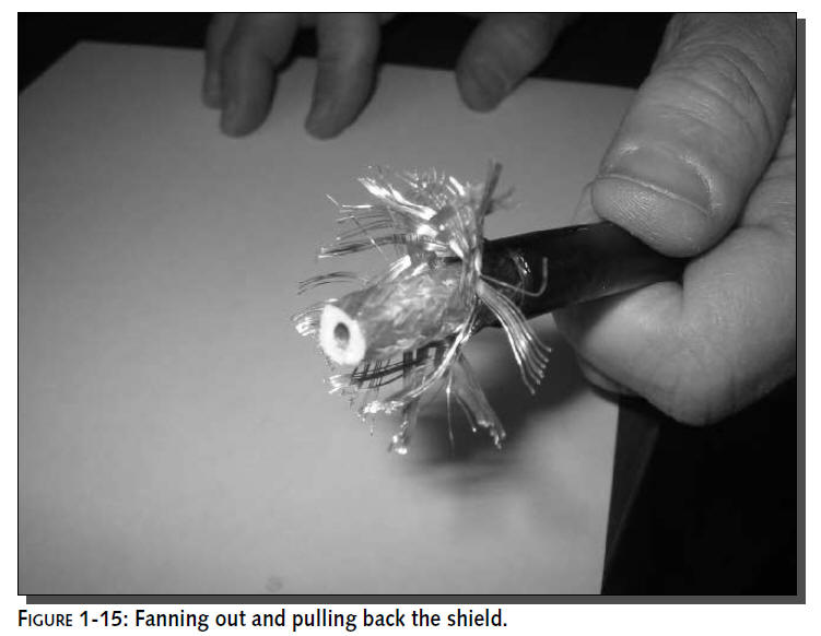
After stripping around the cable, make a groove
along the length of the cable. Make three or four cuts with just
enough force to cut a little deeper each time, as shown in
Figure 1-13. The goal is to come as close to the shield as
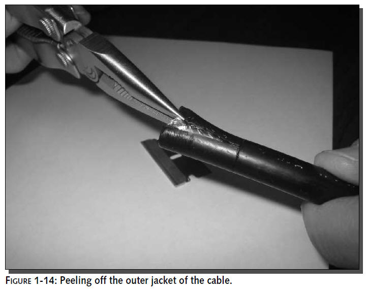
possible without cutting all the way through the cable. Now grab
the end of the outer jacket with a set of long-nosed pliers and
pull away the jacket. Tear along the grooves scored into the
jacket and peel off the jacket with your fingers to reveal the
shield mesh underneath, as shown in Figure 1-14.
Step 4: Pulling Back the Inner Shield
To get the next cut ready, use your fingers to
carefully fan out and pull back the shield mesh layer, as shown
in Figure 1-15.
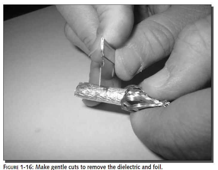
Step 5: Stripping the Dielectric
Now strip off the foam dielectric core along
with the solid aluminum wrapping. This requires much less force
than the cable jacket. Be sure to apply light pressure and try
not to nick the center conductor. (See Figure 1-16.) To remove
the foam core from the center conductor, just twist and pull.
Step 6: Checking for Shorts
At this stage, you need to inspect the cable for
shorts along the dielectric. Remember that the dielectric
material is a nonconductor of electricity. If there is an
electrical short from the center conductor to the outer shield,
the cable will not perform well, i.e. if it works at all. The
easiest way to accomplish this is with a visual inspection.
Check for any stray shielding strands or aluminum foil material.
See Figure 1-17 for an example of foil shorting the center pin.
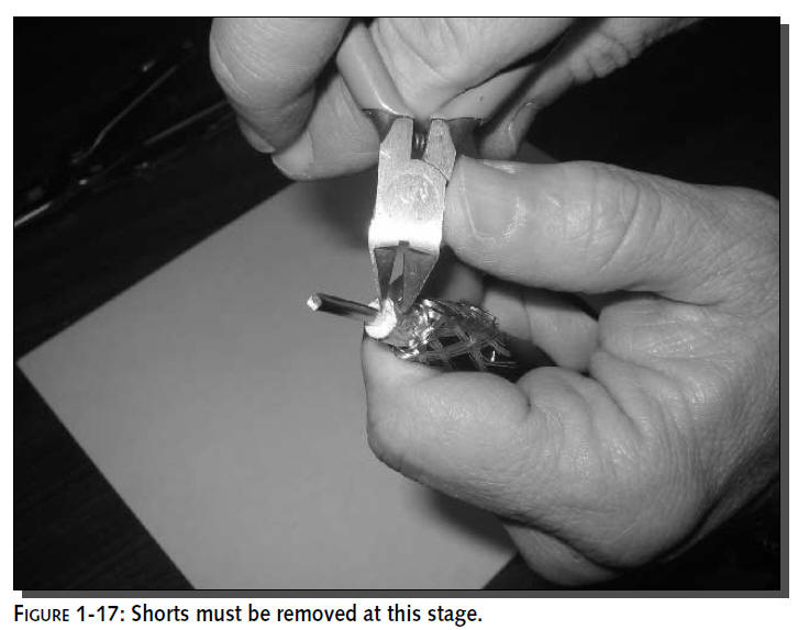
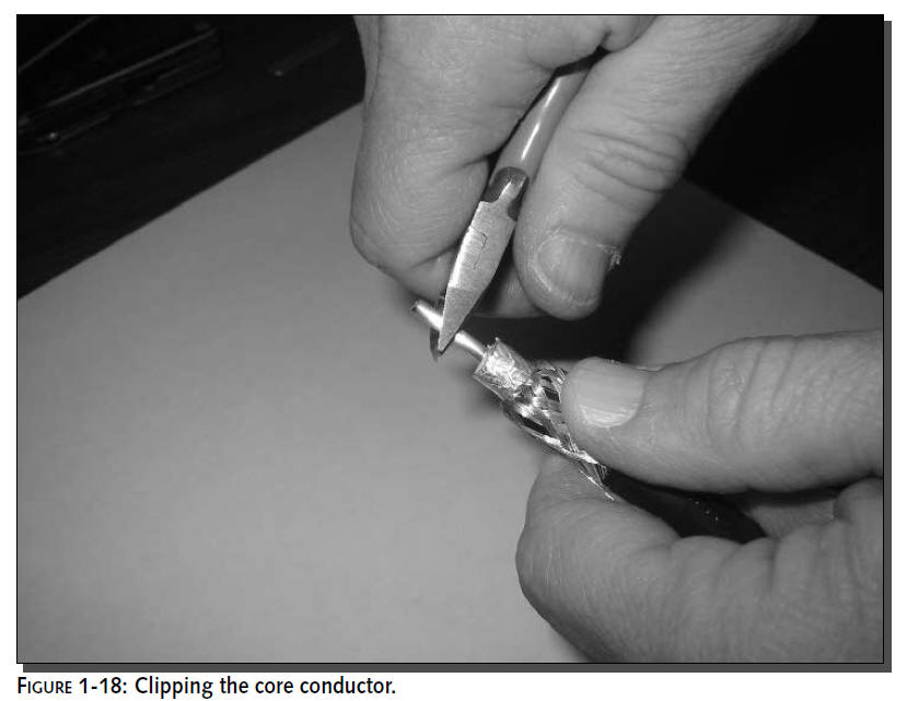
To remove a foil short, use small wire cutters
to scrape away and cut the foam at an angle. You can also use a
fingernail for any smaller, more elusive bits. The corrected
foam should be white all the way around.