To help you pick the right antenna for the job,
first survey the site to get an idea what coverage pattern you
want, and what degree of signal loss you are currently
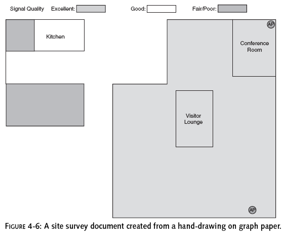
encountering. Start by mapping out the site on a piece of graph
paper, noting possible locations for the high-gain antenna. Then
place the access point (with the existing antenna) in a possible
location, and walk around with your laptop to the areas you want
to cover. If you have NetStumbler on your laptop, you may be
able to use it to measure the signal-to-noise ratio (SNR) in
each desired coverage location.
The higher the SNR, the better. Lacking that,
just note whether the laptop can connect to the network, and if
it can, how long it takes to perform some common tasks, such as
transferring files. See the basic site survey document in Figure
4-6. If nothing else, this will give you a point of comparison,
to determine how much boost you get from your high-gain antenna.
In addition, you’ll probably get a better idea what kinds of
transmission losses you’re experiencing.Typically, you may see
three kinds of losses: propagation losses, multipath losses
(signal fading), and interference.
Propagation loss represents the “resistance” of
whatever the RF has to pass through. Every medium, including
air, has a particular loss at a given frequency. The loss is
proportional to
the distance that the signal has to travel
through the medium. For example, the signal will probably lose
about 6 dB going through a wall with 2-by-4 wood studs and
sheetrock on both sides. Beyond about 20 feet from the access
point, propagation losses can increase at up to 30 dB per 100
feet, depending on building construction and layout. You’ll get
losses not only from walls, ceilings and floors, but even from
furniture and people.
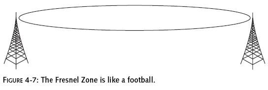
Visualize the signal as half a football, with
the antenna at the point. Beyond 20 feet or so from the access
point, anything that pokes into that area (called the
Fresnel Zone)
will degrade the signal. See Figure 4-7 for an example. Fresnel
Zone incursions are a secondary factor when it comes to
interference. The most critical factor is objects that are in
the direct line-of-sight (LOS) between the access point antenna
and clients. However, objects below the LOS but in the Fresnel
Zone can have a significant effect, as well. That’s why, in
long-distance outdoor installations, antennas are usually
positioned higher than is necessary just for LOS. Outdoors, it’s
standard practice to calculate the size of the Fresnel Zone and
use that to determine how high the antenna should be.
Indoors, antennas may be installed in the attic
or on the ceiling, in order to avoid Fresnel Zone incursions. If
that’s not possible, you just have to get a more powerful
antenna, in order to overcome the losses. Whether you can clear
the obstacles, or whether you just have to compensate for them,
it’s good to know what your Fresnel Zone Clearance is. There are
simple calculators available on the Web that will allow you to
calculate this very quickly. (For instance,
www.thirdheight.com/support/downloads/wireless/SOM_calcs.xls.)
This calculator will help you not only with
Fresnel Zones, but with your overall “link budget,” a
calculation to determine whether the signal transmitted from
your antenna is powerful enough to reach the intended receivers.
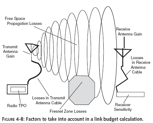
A link budget calculation takes into account a variety of
factors, including TPO, transmit antenna gain, losses in the
transmission antenna cable, free space propagation losses,
Fresnel Zone losses, losses in the receive antenna cable,
receive antenna gain, and receiver sensitivity. Other factors
such as connectors and lightning arresters in the cables can
also be taken into account. (Figure 4-8 shows the variables
involved in a typical link budget calculation.)
A common rule of thumb is that the signal should
be 10 dB stronger than the minimum required for communication.
This 10 dB is referred to as the
System Operating Margin
(SOM).
FIGURE 4-7: The Fresnel Zone is like a football.
Multipath Losses and Interference
Multipath losses occur when signals take
different paths to a receiver. If one path is significantly
longer than the other, the peaks and troughs of the two signals
will be significantly out of sync with one another (“out of
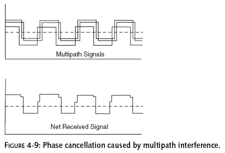
phase”) when they get to the receiver. Signals that are totally
out of phase (180 degrees) will completely cancel one another,
as the troughs of one signal cancel the peaks of the other (see
Figure 4-9). In practice, the phases of the two signals will
usually drift constantly, so the signal cancellation changes,
resulting in a constantly fluctuating signal (“signal fade”).
Having two receiving antennas usually helps substantially. Phase
cancellation will be different for the two antennas, because of
the differences in the length of the two paths required to reach
the antennas.With properly spaced antennas, the signal at one
antenna can be strong when the other is weak.
When you attach a high-gain antenna to an access
point, you lose the advantage of two antennas, and you tend to
increase multipath losses. The high-gain antenna should more
than make up for this, but you may want to take this effect into
account in calculating your antenna gain requirements. If your
connection seems to continuously fade in and out, suspect
multipath losses.
Interference may come from any other equipment
running at 2.4 GHz (including other Wi-Fi networks),
particularly if they’re using the same channel as you are, or
equipment generating broad spectrum RF. Interference is often “bursty”
in nature, as the interfering equipment is seldom operating
full-out all the time. If your network experiences sudden and
seemingly random attacks of deteriorating performance, look for
a source of interference. You may be able to change channels or
locate your network equipment and antenna to get away from the
offending source. Otherwise, you’ll have to up your power to
overcome the interference.