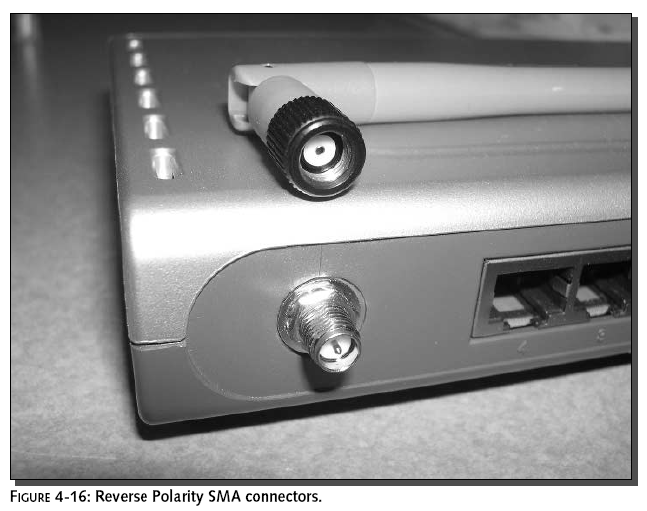
seem to be working correctly, you’ll easily be
able to do tests (such as cable continuity tests) without
running back and forth between the access point and the antenna.
When you do install the cable in its final position, avoid
crimping and excessive bending of the cable. Also avoid possible
sources of interference, which would primarily be other
equipment operating in the 2.4 GHz band (like cordless phones
and microwave ovens), but could include sources of broad
spectrum RF such as fluorescent lights.
The shorter the cable, the better. Consider
locating the access point and the antenna within a few feet of
one another, as this will give you the highest power output for
your antenna. In outdoor installations, this may not be
possible, since you may need to put the antenna in a location
where power cannot easily be run. However, indoors, you should
be able to get power almost anywhere fairly easily, even if it
means running a long extension cord.
Step 4: Position and Install the Antenna
Positioning the antenna may be an iterative
process. If you have multiple possible locations for the
antenna, you’ll want to do some testing in each location before
settling on the best one. Mounting the antenna higher up, like
on a wall or on top of a file cabinet, is usually better. Think
light bulb or flashlight. Does the room light up better when the
light is near the ceiling away from obstructions or down on the
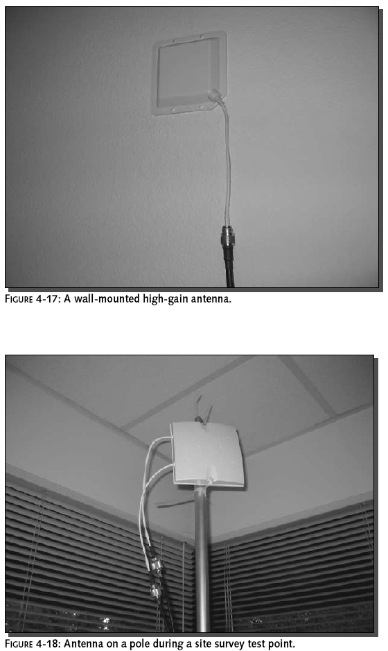
floor behind a desk? Figure 4-17 shows a typical install of a
high-gain antenna.
Do not damage the housing of the antenna, or any
metallic surfaces. Often, an antenna will use a metal backplane
as a reflector to increase the gain. If you drill through that
reflector, the gain will be adversely affected.
As a final step, perform another site survey as
described earlier in this chapter. This time, use the new
configuration with the new antenna. Figure 4-18 shows a site
survey test point with a high-gain antenna.
For maximum mobility, fill a sports bag with a 12-volt
battery, a DC-to-AC inverter, and an access point. The access
point is configured to transmit a beacon so the client can
monitor signal strength. This setup
keeps you highly mobile for hours during the survey—no power
cords.
What About Signal Amplification?
This is an appropriate place to mention the
alternative of using amplifiers, as opposed to antennas, to
boost signals. For instance, Linksys sells a Wireless Signal
Booster (WSB24) that amplifies both transmit and receive
signals.Tests indicate that amplifiers are effective for
improving connection reliability and throughput within your
existing coverage area. However, a high-gain antenna is still
the way to go if you need to expand your coverage (see
www.smallnetbuilder.com/Reviews-38-ProdID-WSB24-1.php.).
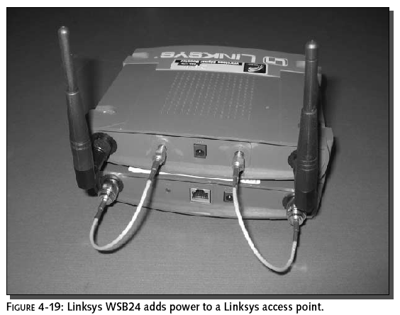
Figure 4-19 shows a test of the Linksys WSB24
using NetStumbler in power monitor mode.
RF signal amplifiers work in different ways.
Make sure you understand the input and output requirements
before investing in an antenna and configuring your access
point. For example, the Linksys WSB24 requires antenna diversity
to be enabled on its input. It then converts the signal to only
transmit through the Right and receive only on the Left antenna
jacks.
Summary
In this chapter, you’ve learned the basics
required to successfully install a high-gain antenna, a process
that is usually not terribly difficult or expensive, and can
yield highly gratifying results. Not only do you have
instructions for installing the antenna, you have a game plan
for doing the job right, determining your equipment needs based
on a site survey, a link budget, and legal and safety
restrictions.
Now that your stay-at-home network is
super-charged, read on to Chapter 5, “Gearing Up for War
Driving,” to learn about taking wireless networking on the
road—peering into the invisible world of wireless networks
operating all around you.