Configuring Your Solar System
To understand the various configurations for solar power, we
will cover a few different applications.
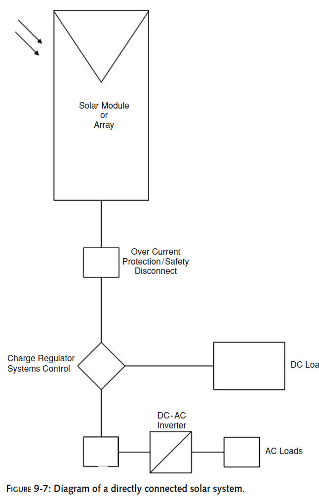
A
directly connected system
is shown in Figure 9-7.
Characteristics:
No
battery storage
Load operates in
sync with sunlight
Peak operation during summer and middle of the day
Special inverter can add AC power
Typical applications:
Ventilation fans
Water pumping
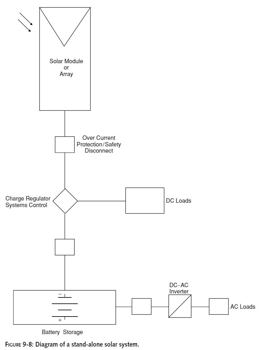
A
stand-alone system
is shown in Figure 9-8.
Characteristics:
Battery storage allows operation at night or during bad weather
Charge regulator prevents battery from over-charging and
over-discharging
System controls can include circuit protection and
remote monitoring
Inverter can add AC power
Typical applications:
Telecommunications telemetry
Outdoor lighting
RV
or boat electric power source
Remote homes or storage facilities
There are also a number of
hybrid systems.
Characteristics:
Generator plus rectifier allows battery charging for full energy
availability in any climate or
season
Generator can be multifuel source (natural gas, diesel, propane)
AC
bus allows direct AC power to loads from generator through
transfer switch, while also
recharging the battery through the rectifier
DC
Bus has all power flowing through battery (DC), avoiding complex
transfer switching and any anomalies in the power load
Typical applications:
Large telecommunications stations
RV
with generator
The wireless repeater in this chapter will be designed using
the stand-alone model.
Installation Overview
The heart of the system is the solar panel,
while the body is the enclosure cabinet. The enclosure will
house all of the electronics and keep them safe from the weather
and other predators. The enclosure will be directly connected to
the solar panel and wireless antennas. Flexible conduit is
recommended for the solar panel junction box interface, while
Times Microwave LMR-400 cabling is suitable for the antenna
connections. If your enclosure has “knockouts” for conduit, so
much the better; otherwise, drill out the holes for your
pigtails and electrical conduit.
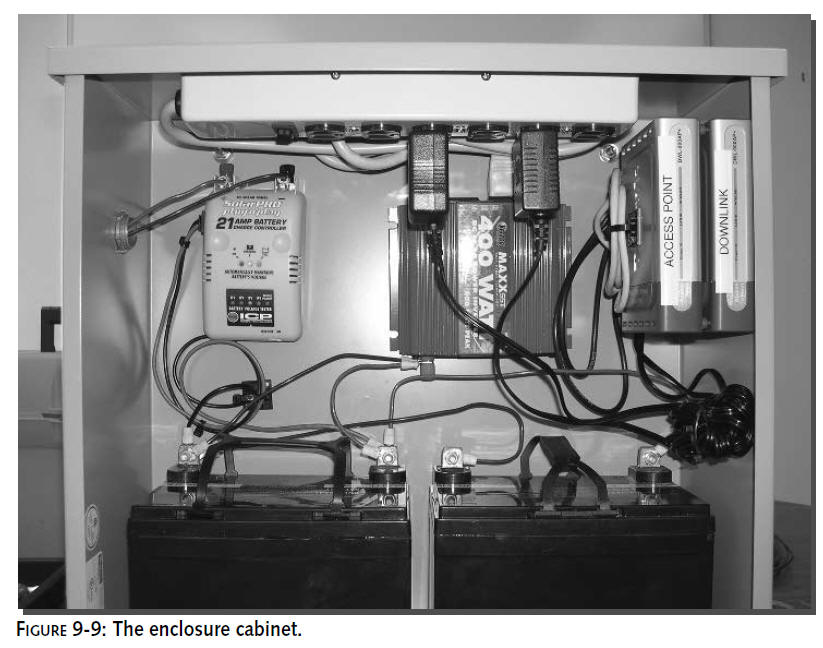
Figure 9-9 shows the enclosure layout.
Components are spaced evenly for ease of maintenance. Electrical
wiring exits the enclosure on the left. Antenna cabling exits on
the right through bulkhead pigtail connectors connected to
LMR-400 cable.
Assembling Your System
Since this system is to be deployed in an
outside remote location, it is recommended that you first unpack
all of your items indoors to ensure that you have all the
required pieces and that they are all in good condition prior to
beginning.
In addition, you may want to build as much of
the control cabinet as possible before deployment to test
components and minimize the number of total items that will
eventually be carried to your destination.
It is critical to closely inspect your PV panel,
because it may be the most fragile and valuable part of this
configuration. Specifically, look for any cracks or breaks in
the glass or framing that may have occurred during the shipping
process. If you notice any irregularities, contact your dealer
for immediate replacement. Once you are satisfied that all the
contents are present and in reasonable condition, you are ready
to begin.
You should start by assembling the contents of
the control cabinet first. This is due to its complexity, and it
is the core of your system. Once all of the items are mounted
and wired into the cabinet, the balance of the installation will
require little more than erecting the pole, mounting the PV
panel, control box, and antennas to the pole, and then testing.
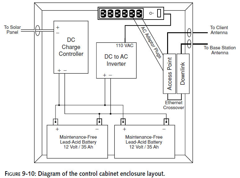
Figure 9-10 shows a diagram of the cabinet layout for this
installation.
For ease of installation, and to simplify future
maintenance requirements, various lengths of Velcro Strips are
part of the list of materials. This Velcro will be used in place
of drilling, nuts and bolts. Moreover, this approach will
eliminate the need to punch holes into your control cabinet
which could later result in problems from leakage.
For that professional look and feel, use an
enclosure with built-in standoffs and a mounting panel. The
panel becomes a backboard for drilling and mounting equipment
without piercing the rear of the cabinet.
The cabinet used in this chapter is an 18 inch
�
18 inch
�
6 inch enclosure (18
inches square and 6 inches deep).We
drilled the holes necessary for the pigtails with bulkhead
connectors and for the solar panel
conduit. Angle iron was used to adapt the cabinet for U-bolt
pole mounting.
Hundreds of cabinets are available from
suppliers like Hammond and B-Line. Search the Internet for these
companies, or visit the wireless supply companies like
Tessco,Talley, and Electrocom.
Step 1: Install the Battery Cell
Install the battery (or batteries in this case)
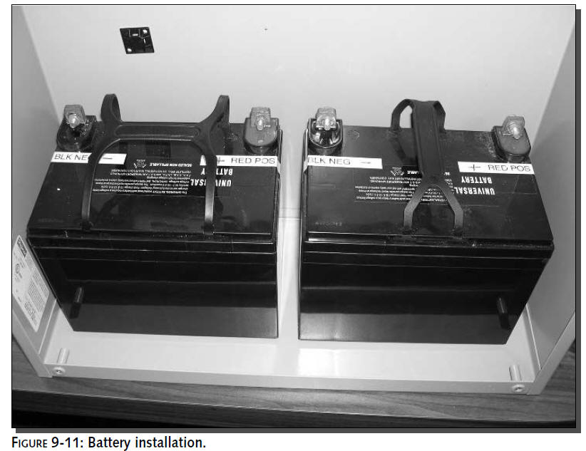
into the cabinet, as shown in Figure 9-11. Apply 4-inch Velcro
strips to the battery cell, one strip on each end, and apply
corresponding Velcro strips to the bottom of the control
cabinet. Finally, insert the battery cell into the control
cabinet and test alignment of battery with respect to the
cabinet. Be sure that the battery is not touching either side of
the cabinet and the space is relatively equal from side-to-side.
Charge the batteries before installing them into
the cabinet. A standard car charger set to tricklecharge the
battery should work fine for topping them off before “the great
on-turning.”
Step 2: Install the Charge Controller
Refer to your internal cabinet diagram for
component orientation and organization. You may choose to design
your cabinet differently, and that is fine, just ensure that you
have a proper cable management plan before you get too far into
the project. This is extremely important in future days and
weeks when maintenance procedures may be required and taking
parts in and out could be hampered by inefficient arrangements.
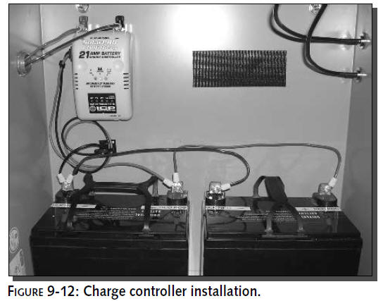
Figure 9-12 shows the charge controller in place. Substantial
Velcro adhesive holds the charge controller in place.
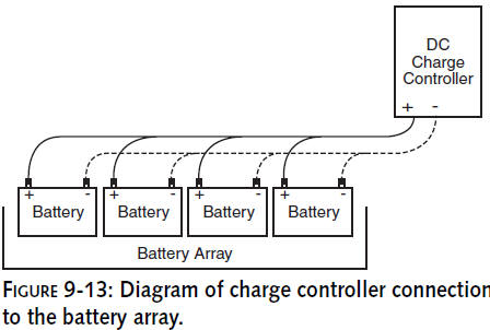
Wiring from the charge controller connects
directly to the batteries as shown in Figure 9-13. When
connecting multiple batteries, connect only the negative (
�)
terminals to each other, then
connect only the positive () terminals to each other. Do not
cross the streams! This is a parallel
connection where voltage remains the same (12 V) but the
current capacity increases (70 Ah).
Only connect positive () to positive () and
negative (
�)
to negative (�).
Do not short-circuit the battery. Just like a car battery, these
batteries need to be treated with care and connected
properly.
Step 3: Install the DC-to-AC inverter
The DC-to-AC inverter converts the DC battery
power into AC power for the power strip and wireless components.
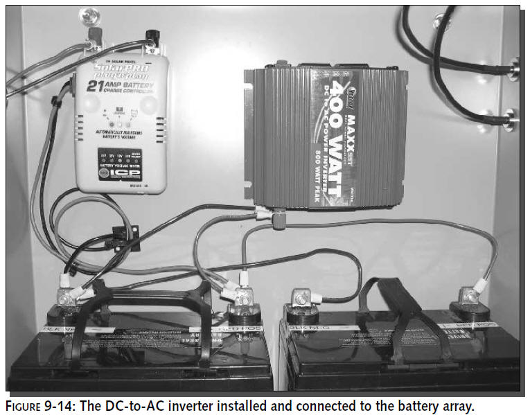
The battery directly connects to the DC inputs on the inverter.
Figure 9-14 shows the inverter installed and connected to the
battery.
By choosing to use an inverter to provide
universal AC power, you have the option of easily changing out
radio equipment. Also, while on-site at the repeater system,
extra AC power comes in handy.
When choosing a DC-to-AC inverter, a low-cost
“modified sine wave” inverter works fine with this type of
equipment. However, parasitic power is a factor. Try to find an
inverter with low internal current consumption. Anything with
less than 0.2 A (200 mA) is fine.
As you may have noticed, the charge controller
and the inverter are both connected to the battery. Solar energy
is used to charge the battery via the controller, while
simultaneously, the inverter pulls electricity out of the
battery for the wireless radios.
Step 4: Install the Wireless Radios
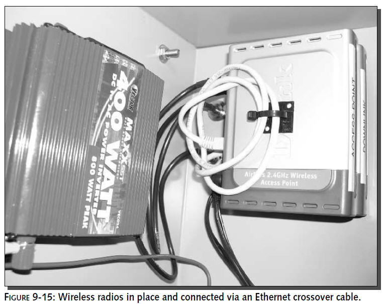
The wireless equipment will be stacked with the
access point on top of the bridge, so keep that in mind as you
begin to install this component. Additionally, the radios will
be AC-powered devices, and you will need to route the power
cords so that they can cleanly access the power strip that will
be mounted shortly.
You will clearly need to modify this step if
your product is a single-board computer with integrated radios,
like a Soekris or open brick computer described in Chapter 8.
Products from the same manufacturer will often
be designed with cases that make stacking a cinch. Consider this
fact when selecting the access point and bridge devices.
Connect the radios via an Ethernet crossover cable.
Remember the configuration is for the
access point to connect back home via the wireless
bridge. If the bridge is configured correctly, the access point
should believe it is sitting on the wired network back at the
bottom of the downlink. Figure 9-15
shows the radios mounted and connected.
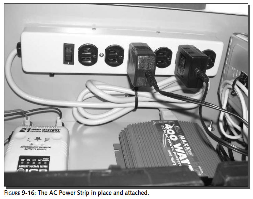
Step 5: Install the AC Power Strip
The installation of a power strip will add
enormous convenience and flexibility in your system. Not only
will it be responsible for supplying power to your critical
communications devices, but it will also give you the ability to
serve any other electronic device that meets the output
requirements this system has been designed for.
For instance, you will be able to operate low
power tools, temporary lighting, cell phone and laptop chargers
and any other AC-powered convenience devices that may become
useful during the installation.
Your AC Power Strip will be mounted to the top
of the cabinet (see Figure 9-16).We recommend attaching it the
way you did all the other devices, with Velcro as the primary
fastener. Adding a third strip of Velcro to the middle of the AC
Power Strip and to the corresponding place on the cabinet back
wall will add stability since this device will be subject to
more strain from plugs being inserted and removed. You are
certainly welcome to use two-sided tape, but we don’t recommend
drilling holes through the exterior of the cabinet. Any water
leakage in this area could be hazardous to the equipment.
At this point, your cabinet should be fully
populated. Charge the batteries by using a 12-volt power source
attached to the leads of the charge controller. Anything
supporting a few amperes at 12 V is acceptable. A car battery
charger set to low-current trickle-charge works fine.
When charging the battery, check the status
lights on your charge controller. There should be a “power on”
indicator along with a “battery charging” light.When the
batteries are topped off, the “battery full” light will come on.
Do not apply more voltage or current than the
charge controller is rated to handle. The controller used in
this chapter (shown earlier in Figure 9-13) is rated for 12 V
and 21 A. We charged the batteries with a 12 V, 4 A source to
match the solar panel output.
Once charged, you can remove the batteries and
other components for ease of installation and travel. As you’ve
already noticed, Most of the weight in this system comes from
the batteries.