Making the transmitter circuit and remote
control box
The transmitter circuit fits into a remote
control box and allows you to turn Sam on and off, speed him up
or slow him down, and sound his horn. Here’s what’s involved in
making this circuit:
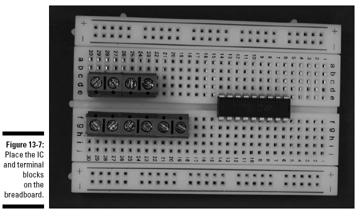
1. Place HT12E (IC1) and five terminal blocks on
the breadboard, as shown in Figure 13-7.
The five terminal blocks shows in this figure
will be used to connect two wires each to various components in
the circuit. The wires from these terminal blocks will go to the
battery pack, the on/off switch, the transmit switch, and the
three toggle switches.
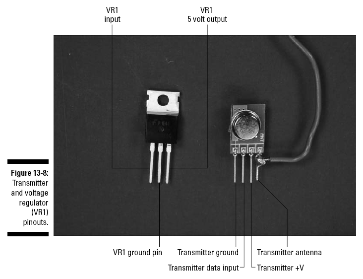
2. Solder an antenna wire to Pin 4 of the
transmitter module, as shown in Figure 13-8.
See the earlier “Building Alert: Construction
Issues” section of this chapter for some tips on how to do this.
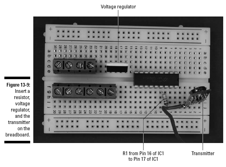
3. Insert the voltage regulator (VR1), a 1
megohm resistor (R1), and the transmitter module on the
breadboard, as shown in Figure 13-9.
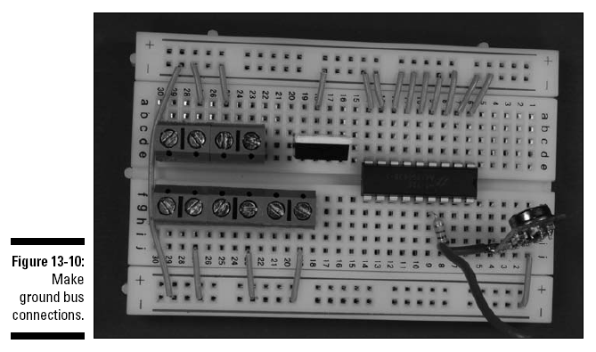
4. Insert wires to connect the IC, voltage
regulator, transmitter, and the terminal blocks to the ground
bus. Then insert a wire between the two ground buses to connect
them, as shown in Figure 13-10.
Sixteen shorter wires connect components to
ground bus; the long wire on the right connects the two ground
buses.
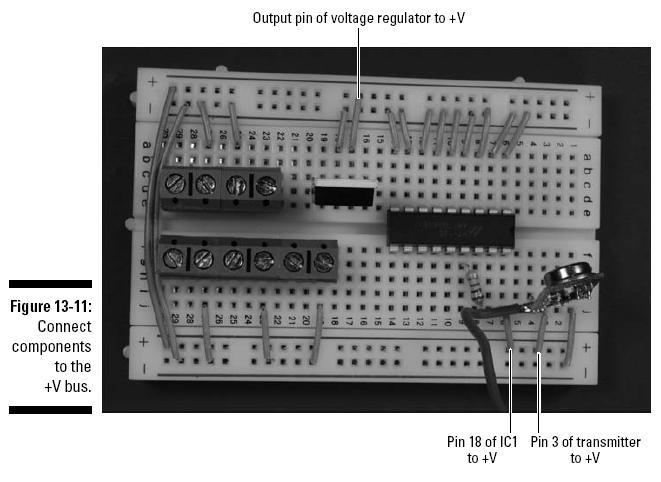
5. Insert wires to connect the IC, voltage
regulator, and transmitter to +V; then insert a wire between the
two +V buses to connect them, as shown in Figure 13-11.
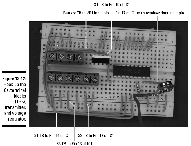
6. Insert wires to connect the IC, voltage
regulator, transmitter, and terminal blocks, as shown in Figure
13-12.
The next step is to drill all kinds of holes
into which you can pop various components to create the remote
control box. Follow these steps to do so:
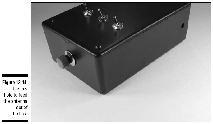
1. Drill holes in the box where you will mount
the on/off switch, speed switch, horn switch, start/stop switch,
transmit switch, and antenna, as shown in Figures 13-13 and
13-14.
You can rearrange the switches. Just be careful
not to put a switch where it will be in the way of the battery
pack when you mount it inside the box.
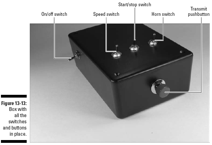
On the end of the right side of the box, you can
see the hole used to feed antenna out of box.
See Chapter 4 for more information about
choosing drill bit sizes for particular components. In that
chapter, we also offer advice about how to customize a box for
your projects. Make sure you use safety glasses when drilling,
and clamp the box to your worktable!
2. Slip the shaft of the switches through the
drilled holes and secure with the nuts provided.
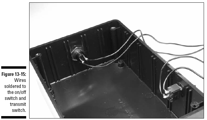
3. Solder the black wire from the battery pack
to one lug of the on/off switch and solder an 8" black wire to
the remaining lug of the on/off switch, as shown in Figure
13-15.
4. Solder an 8" wire to each of the two lugs on
the pushbutton transmit switch, as shown in Figure 13-15.
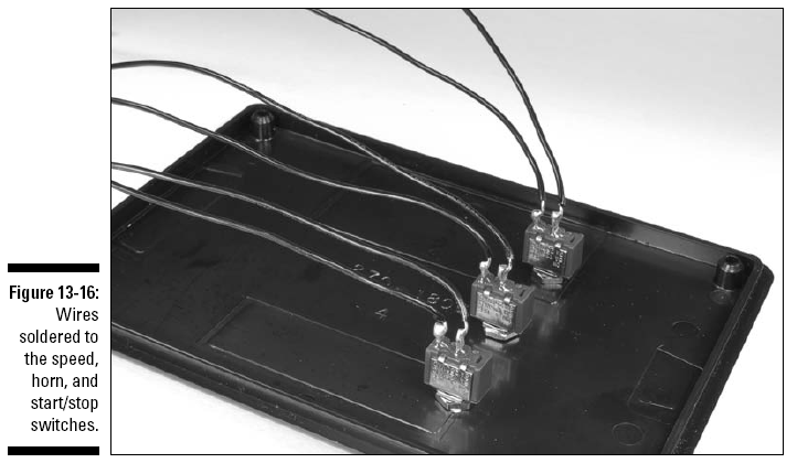
5. Solder 6" wires to each of the two lugs on
each of the three switches mounted on the cover, as shown in
Figure 13-16.
If you have 22 gauge stranded wire, consider
using it for connecting the switches mounted on the cover.
Stranded wire is more flexible, which makes getting the cover on
the box easier. As we discuss in Chapter 4, solder the end of
the stranded wire to gather all those loose strands.
Repeat after us: Heed all the safety precautions
about soldering that we give you in Chapter 2. Use adequate
ventilation when soldering to avoid inhaling fumes, and be sure
to get a soldering iron with a stable stand so there’s no danger
of it falling off your work surface.
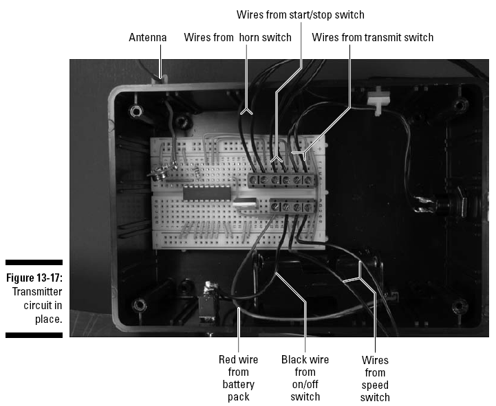
6. Secure the breadboard and battery pack in the
box with Velcro, as shown in Figure 13-17.
As you place the breadboard in the box,
carefully feed the antenna wire out of the box through its hole
and secure the antenna wire with a wire clip.
7. Attach the wires from the battery pack,
on/off, transmit, speed, horn, and start/stop switches to the
terminal blocks, as shown in Figure 13-17.