Scoping Out the Schematic
You need to get your arms around two schematics
to master this project. The first is the transmitter circuit
that you use to send Sam his commands. The second is the
receiver circuit that helps him understand what the heck you’re
saying!
Transmitting Sam’s commands
You use the transmitter circuit to send signals
to Sam to start, change speeds, and sound his horn. Here’s an
explanation of what’s going on in this circuit:
VR1 is a
voltage regulator that takes the 6 volts supplied by the battery
pack and supplies a steady 5 volts instead. We added this
because although the IC specs say
it should work with 6 volts, it blew out the
first time we tried using 6 volts. Better safe than
sorry!
The
transmitter
module sends
out a radio signal at 433.9 MHz that’s
modulated with the code provided by the encoder.
IC1 is an
encoder. The radio signal that the remote control sends out is
modulated, depending upon how you have the switches set,
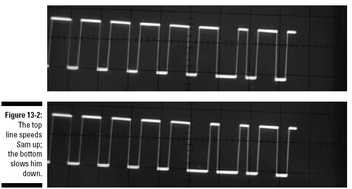
by this encoding IC (see Figure
13-2). In this figure, the top line shows the code
that tells Sam to speed up, and the bottom shows the code
that tells Sam to slow down, based in the width of the fourth
pulse from the right. The radio
receiver in Sam sends this code to a decoding IC to turn Sam
on/off, honk the horn, or change the speed.
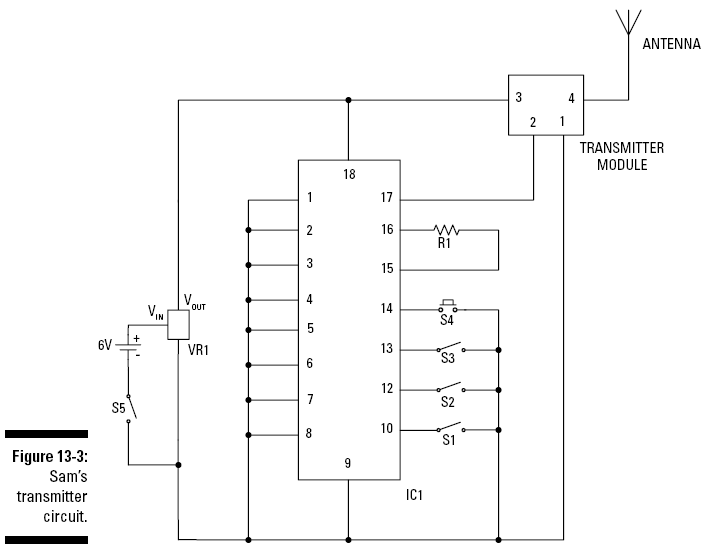
Pin 14 is a
transmit enable pin. When you press the normally open (NO)
pushbutton switch between Pin 14 and ground, the encoder
sends a signal to the transmitter
module. This signal contains information that
tells the decoding module whether the toggle switches
(S1–S4) between Pins 10, 11, 12, and 13 and ground are open or
closed.
R1 is a
resistor that sets the frequency of an oscillator that’s
internal to the encoder. The signal
from this oscillator is required to generate the
encoded signal.
S5 is the
on/off switch.
Figure 13-3 shows what’s going on in the
transmitter circuit.