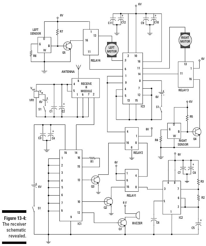
Helping Sam receive his commands
The receiver circuit that Sam uses to make sense
of all your transmitted commands is shown in Figure 13-4. Here’s
how this one works:
The
receiver module
separates the
coded signal sent by the transmitter
from the 433.9 MHz carrier wave. The output of the
receiver module at Pin 2 is the
decoded signal, as shown in Figure 13-2.
VR1 is a
voltage regulator that takes the 6 volts supplied by the battery
pack and supplies a steady 5 volts because the
transmitter module has a maximum
voltage of 5.5 volts. We provided a separate battery pack for
this section of the circuit to provide a stable supply
for the radio receiver.
We found this setup gives much more consistent
reception than setting up the receiver to share a battery pack
with the rest of the circuit.
S1 is the
on/off switch for the circuit.
IC1 decodes the
signal sent by the transmitter. Pins 10, 11, 12, and 13 are
outputs of the decoder that are at 0 volts if the
corresponding toggle switch on the
encoder is
closed
(connected to ground). The outputs are
at about 5 volts if the corresponding toggle switch on
the encoder is
open
(not connected
to ground). These outputs stay at one voltage until
they receive another signal to change.
The
10 microfarad
and 0.1 microfarad capacitors
(C1–C4 and C7–C12)
placed between the +V and ground buses at the +V input of
each of the ICs are used to filter
electrical noise from the DC motors. That noise can
prevent the ICs from getting the correct supply voltage.
IC2 is an LM555
timer that generates a square wave at Pin 3. This square
wave alternates between 5 volts and 0 (zero) volts. The
frequency of the square wave is
determined by the values of
R2, R3,
and
C5;
we discuss
this process in Chapter 9. When you tell Sensitive Sam to
slow down, this square wave causes
the voltage to the motor to switch on and off
rapidly, with 6 volts to the motor half the time and 0
volts to the motor half the time.
When you ask Sam to speed up, 6 volts are sent to the motor
constantly. This is a simple form of
pulse width
modulation,
which is commonly used to control
the speed of DC motors.
C6 is a
capacitor that reduces the occurrence of noise on Pin 5 of IC2,
which could cause false triggering of the LM555. This
might occur if Pin 5 were left
unconnected.
Q1 turns the
horn on and off. Q1 is a transistor that turns on when
decoder Pin 12 is at 5 volts. Turning on Q1 allows a
current to flow through the buzzer.
To turn on the buzzer, you put the toggle switch connected
to the encoder Pin 12 on the transmitter in the open
position and push the transmit button. To turn off the buzzer,
you put the toggle switch connected
to encoder Pin 12 on the transmitter in the closed
position and push the transmit button.
Q2 and
Relay 1
control Sam’s speed. Q2 is
a transistor that turns on when
decoder Pin 10 is at 5 volts. Pin 4 and Pin 6 are normally
connected (NC), and Pin 4 and Pin 8
are normally open (NO). Turning on Q2 allows current to flow
through the coil in Relay 1 and connects Pin 4 to
Pin 8. Pin 4 is the output of Relay 1, and Pin 8 is where
you input the square wave from IC2
into Relay 1. When Q2 is off, no current flows through the coil
in Relay 1, and Pin 4 is connected to Pin 6. This makes the
output of Relay 1 approximately 5 volts. To ask Sam to go full
speed
ahead, you put the toggle switch connected to
the encoder Pin 10 in the closed position and push the transmit
button. To ask Sam to slow down, you put the toggle switch
connected to the encoder Pin 10 in the open position and push
the transmit button.
Use
Q3
and
Relay 2
to tell Sam to start or
stop. Q3 is a transistor that turns
on when decoder Pin 13 is at 5 volts. Turning on Q3 by having
the start/stop transmitter toggle
switch closed allows current to flow through the coil in Relay 2
and connects Pin 4 (the output of Relay 2) to Pin 8. This tells
Sam to run his engines. When the start/stop transmitter
toggle switch is open and Q3 is off, no current flows
through the coil in Relay 2, and
Pin 4 is connected to Pin 6; this makes the output of Relay 2
zero (0) volts.
IC3 is an
H-bridge motor controller. Although this controller is capable
of controlling more functions than just going straight
ahead (as you can read about in
Chapter 11), all we need it to do here is supply the voltage
to drive each motor forward. The battery pack attached to
Pin 8 of IC3 supplies power for the motors. You connect the
output of Relay 2 to the enable
pins (1 and 9) of IC3. When 5 volts is provided by Relay 2 to
the enable pins, IC3 supplies power
to the motors. When 0 volts is connected to the enable pins, IC3
doesn’t supply power, so Sam just sits there.
The
left and right
sensors allow
Sensitive Sam to take control of himself.
When the track curves or Sam drifts so that one of the
sensors is over the black
electrical tape, power is cut to the motor on that side. This
causes Sam to move away from the tape. When the sensor
again hovers over a reflective floor, power is restored to that
motor, and Sam straightens out.
On the schematic, the orange (O) and green (G)
wires connect to an LED, with
R4
and
R6
limiting the current to
protect the LED from damage. The
blue (B) and white (W) wires connect to a phototransistor.
When the sensor moves over a reflective surface,
such as hardwood floor, the phototransistor is on, and the base
of
Q5
or
Q4
is connected to
ground. This turns off Q5 or Q4, which leaves the output
of Relay 3
or
Relay 4
connected to Pin 11,
allowing the motor to run. When the sensor
is over a nonreflective surface, such as black electrical
tape, the phototransistor is off,
and the base of Q5 or Q4 is connected to a positive voltage
through
R7 or
R5,
turning on Q5 or Q4. This
disconnects the output of the relay
from Pin 11 and also shuts off the motor.