Perusing the Parts List
We broke down the parts shopping list into two .
. . um . . . parts: a list for the transmitter circuit parts and
a list for the receiver circuit and container parts.
Tallying up transmitter bits and pieces
The circuit that sends signals to Sam telling
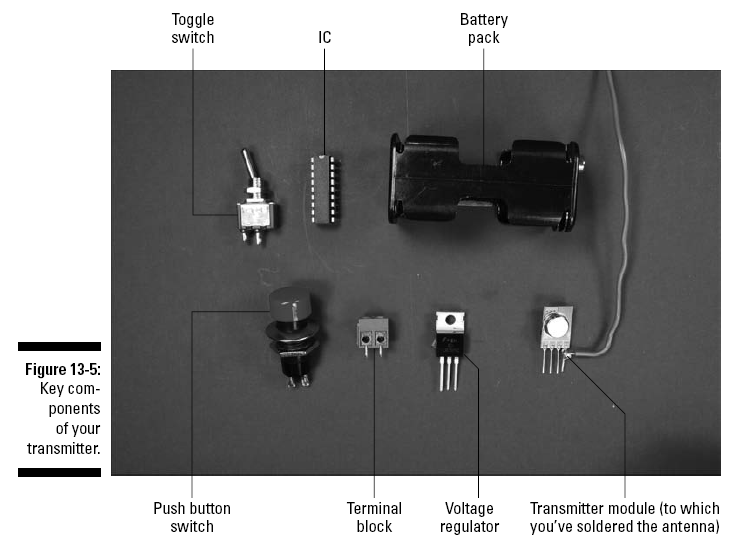
him what to do involves the following parts, several of which
are shown in Figure 13-5:
LM7805 5 volt voltage regulator (VR1)
Four SPST toggle switches (S1, S2, S3, S4)
SPST normally open (NO) momentary push button switch (S4)
Holtek HT12E encoder (IC1)
1 megohm resistor (R1)
TWS-434 RF transmitter module
We bought this at Reynolds Electronics (
www.rentron.com);
Hobby Engineering (www.hobbyengineering.com)
carries a similar module.
400-contact breadboard
One 4 AA battery pack with snap connector
Five 2-pin terminal blocks
Plastic box
We use Radio Shack part #270-1806.
An assortment of different lengths of prestripped short 22 AWG
wire
Running down receiver
and container parts
The circuit that takes transmitted signals and
explains to Sam what’s expected
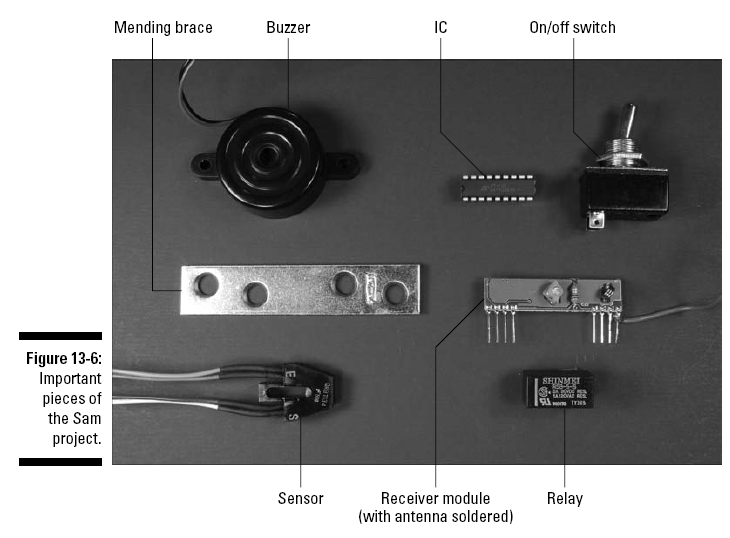
of him involves the following parts, several of
which are shown in Figure 13-6:
Holtek HT12D decoder (IC1)
L293D H-bridge (IC3)
LM555N-1 timer (IC2)
Five 2N3904 transistors (Q1–Q5)
6 volt buzzer
RWS-434 RF receiver module
We bought this at Reynolds Electronics; Hobby
Engineering carries a
similar module.
Four 1 amp or greater solid state relays, DPDT
(double-pole, doublethrow)
or SPDT
(single-pole,
double-throw)
We used the Shinmei RSB-5-S DPDT that we found
at Jameco (
www.
jameco.com
).
A SPDT would also work, but we used the DPDT because
it allows for more flexibility for which side of
the relay we could run
wires to. Make sure that the relay you buy has a
pinout pattern that fits a
breadboard; many of them do not.
Two DC gear motors GM2 each with a 25⁄8"
wheel or equivalent
We use these because the suppliers (Hobby
Engineering (
www.hobby
engineering.com
)
or Solarbotics Ltd. (www.solarbotics.com)
carry wheels made to fit them.
Two metal brackets used as motor mounts
We found 3" x
5⁄8"
mending braces made by National Manufacturing
Company at our local hardware store. These
worked great.
One 11⁄2"
inch swiveling castor
Six 0.1 microfarad ceramic capacitors (C1, C3, C6, C7, C9, C11)
Six 10 microfarad electrolytic capacitors (C2, C4, C5, C8, C10,
C12)
51 kohm resistor (R1)
Three 10 kohm resistors (R3, R5, R7)
Two 150 ohm resistors (R4, R6)
330 ohm resistor (R2)
Two 830-contact breadboards
Two Fairchild QRB1134 sensors
Three 4 AA battery packs with snap connectors
Ten 2-pin terminal blocks
Four 8-32 11⁄2"
panhead screws
Four 8-32 nuts
Four 6-32 1⁄2"
panhead screws
Four 6-32 nuts
Four 4-40 3⁄4"
panhead screws
Four 4-40 nuts
Two wooden boxes
• 2" wide x 5" tall x 1
1⁄4"
deep
• 5
1⁄2"
wide x 81⁄2"
long x 21⁄2"
deep
We found one at a local craft supply store that
was just the right size to
hold the electronics for this project and a
smaller wooden box to glue on
the front of the bigger box to mount the
sensors.
An assortment of different lengths of prestripped, short 22 AWG
wire