Building Sensitive Sam’s chassis
If you’re a sensitive guy like Sam, how your
body looks is very important to you. Here are the steps to build
Sam a serviceable little chassis to hold the receiver circuit:
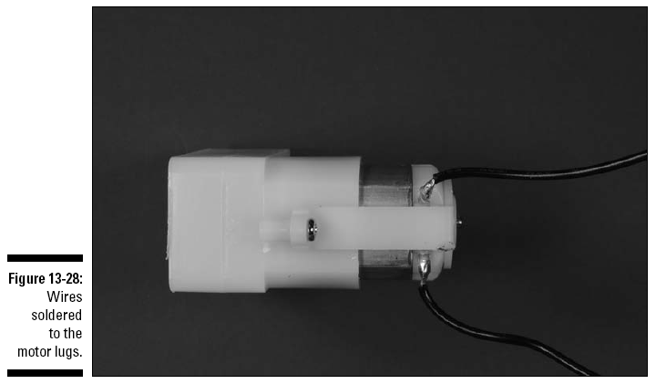
1. Solder 12" stranded wires to the motor lugs,
as shown in Figure 13-28.
2. Drill holes for the 6-32 screws used to mount
the castor, as shown in Figure 13-29.
Use the base of the castor to guide you when
marking the four holes you will drill in the chassis box to
mount the castor
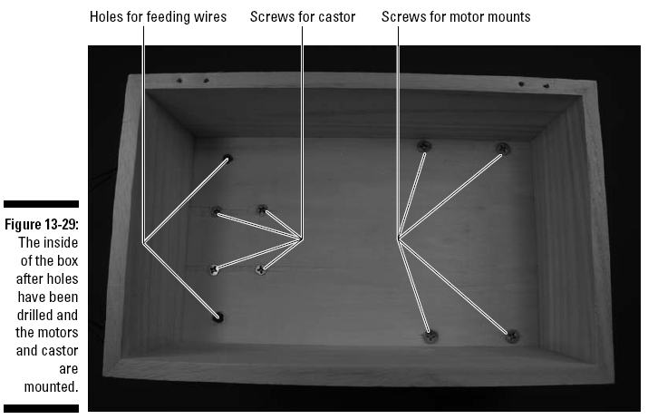
3. Mark a location about an inch to each side of
the castor and drill holes with a 1/4" bit to feed the wires to
the motors and sensors, as shown in Figure 13-29.
4. Using a mending brace to mark the four holes
you will drill in the box to mount the motors, drill holes for
8-32 screws, as shown in Figure 13-29.
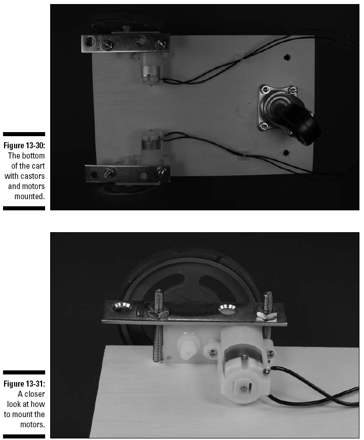
5. Attach the castor to the box with four 6-32
screws and nuts, as shown in Figure 13-30.
6. Attach the motors to the box with two 8-32
screws and nuts and one mending brace for each motor, as shown
in Figures 13-30 and 13-31.
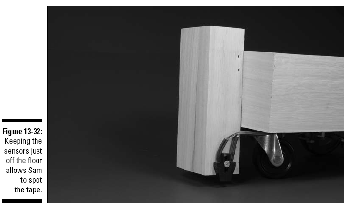
7. Drill a hole for 4-40 screws in each side of
the small box to mount the sensors, as shown in Figure 13-32.
8. Mount the sensors in the small box with one
4-40 screw and nut per sensor.
9. Feed the wires for the sensors and the motors
through the holes you drilled to each side of the castor.
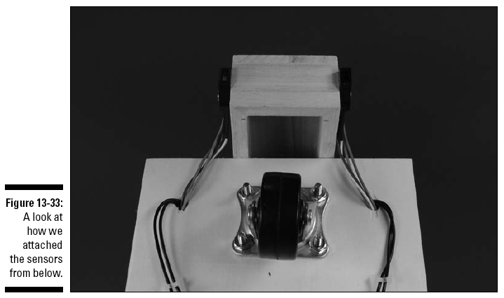
10. Glue the small box to the cart, as shown in
Figures 13-32 and 13-33.
The face of the sensors should be a quarter-inch
above the floor.
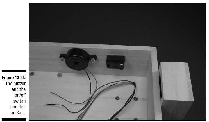
11. Drill two holes for 6-32 screws to mount the
buzzer, as shown in Figure 13-34.
12. Mount the buzzer by using two 6-32 screws
and nuts.
13. Drill a hole in the box where you will
insert the on/off switch, as shown in Figure 13-34.
14. Slip the threaded shaft of the on/off switch
through the hole you drilled and secure it with the nut
provided.
If the wall of the box is too thick to allow the
threads on the switch to reach the nut, use a small chisel to
remove enough wood from the inside wall of the box so that the
nut can engage the threads.
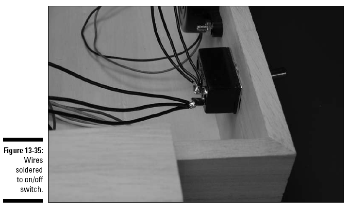
15. Solder the black wires from the three
battery snaps to one lug of the on/off switch and solder three
12" black wires to the other lug of the on/off switch.
Figure 13-35 shows the switch after soldering.
16. Attach Velcro to the breadboard and the box
and secure the breadboard in the box.
17. Attach Velcro to the battery packs and the
box and secure the battery packs in the box.
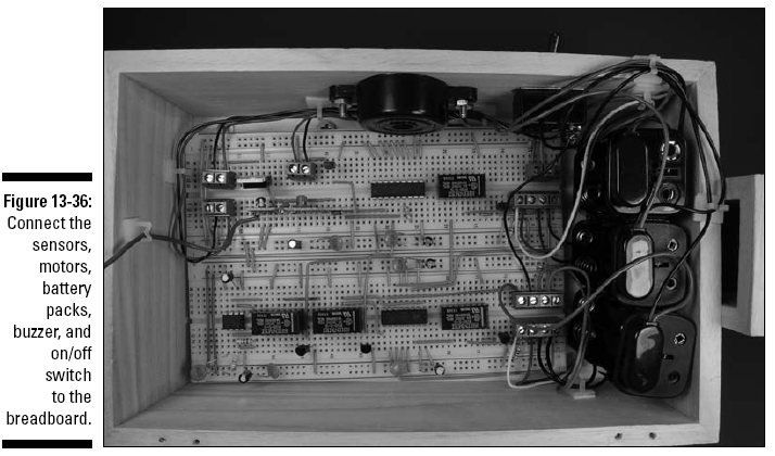
18. Insert the wires from the sensors, motors,
battery packs, buzzer, and the on/off switch to the terminal
blocks on the breadboard, as shown in Figures 13-36 and 13-37.
As you insert the wires, cut each of them to the
length you need for them to reach the corresponding terminal
block. Also, strip the insulation from the end of the wire.
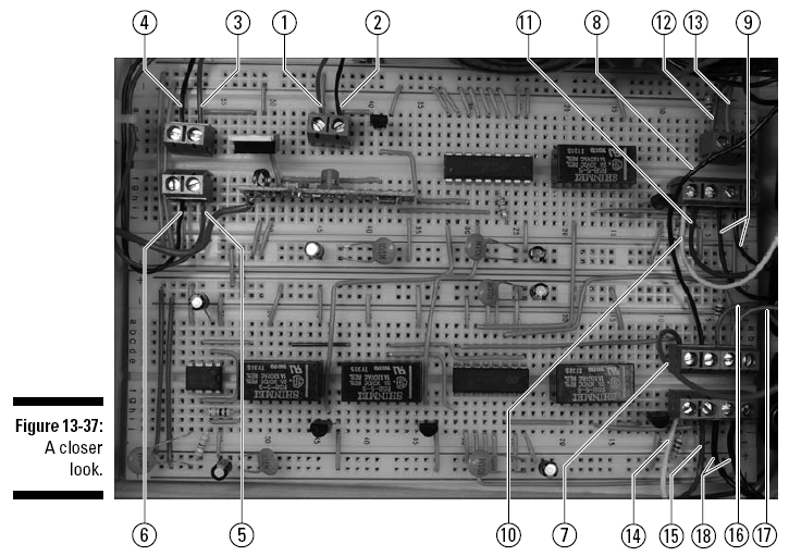
Use the following key for the callouts in Figure
13-37.
1. Red wire from buzzer
2. Black wire from buzzer
3. Red wire from receiver battery pack
4. Black wire from receiver battery pack
5. Red wire from main battery pack
6. Black wire from main battery pack
7. Red wire from motor battery pack
8. Black wire from motor battery pack
9. Wires from left motor
10. White wire from left sensor
11. Blue wire from left sensor
12. Green wire from left sensor
13. Orange wire from left sensor
14. White wire from right sensor
15. Blue wire from right sensor
16. Green wire from right sensor
17. Orange wire from right sensor
18. Wires from right motor
19. Secure the wires with wire clips where
needed.
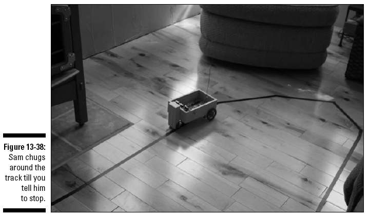
Sensitive Sam is shown roaring around our living
room floor in all his glory in Figure 13-38.
Trying It Out
Now that you have a remote control unit and
Sam’s body all assembled, take him out for a spin. Follow these
steps to play with your new sensitive buddy:
1. Place black electrician’s tape on a
reflective floor (hardwood or linoleum, for example).
You don’t have to create a straight line; you
can use several pieces to design a circular or oval track.
2. Place Sam on the track with the sensors on
either side of the tape.
3. Put batteries in Sam and the remote control
flip the on/off switches on both to On.
4. Flip the start/stop switch to start and press
the transmit button on the remote control to get Sam moving.
5. Flip either the speed or horn switch on the
remote control and then press the transmit button to activate
either effect.
6. To stop Sam, flip the start/stop switch to
stop and press the transmit button.
If nothing happens, here are a few things to
check out:
All
the batteries are fresh, are tight in the battery pack, and face
the right direction.
See
whether any wires or parts have come loose.
Compare your circuit with the photos in this chapter to make
sure you got all the connections
right.
If Sam gets going but doesn’t follow the track
as you expect, you can adjust the sensors by loosening the
screws and sliding the sensors up or down.
If Sam stalls, try these steps:
1. Put the start/stop switch in the start
position.
2. Push the transmit button once more.
Taking It Further
We’re sure you can see why this neat little guy
is Earl’s favorite project. You can create huge tracks and have
him follow around the room. He confuses recalcitrant cats (refer
to Figure 13-1), and you can put notes in his cart and send them
to someone else on the other side of the room.
When you’re ready to take Sam further, try these
suggestions:
Build a Sensitive Samantha using a different radio frequency
module for the remote control to give Sam a girlfriend he can
race with around the track.
Add
lights by using the fourth pin on the encoder/decoder to
control them.
Read up on other radio control project ideas at sites such as
www.renton.com.
If
you build Sam’s chassis to be strong enough, you can put him to
work carrying things around your
house — a can of soda, the TV remote, or
whatever you want to send off to the couch potato
lounging in your living room.