

Murmuring Merlin
Scoping Out the Schematic
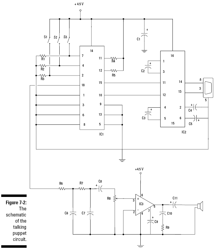
You have only one breadboard to put together for this project. You can see the schematic for the board in Figure 7-2. The following is a list of the schematic elements for our Murmuring Merlin.
IC1 is a SpeakJet sound synthesizer model. You can connect this IC to your computer and program it to generate electrical signals by using software supplied by the manufacturer. These signals correspond to words that form sentences, sounds that create music, or various cool sound effects. The software allows you to program eight sounds; each sound is controlled by one of the Pins 1–4 and 6–9 of the IC. C1 is a capacitor that filters noise from the +4.5V supply to IC2. Switches S1, S2, and S3 control the voltage on Pins 2, 4, and 7. The switches are normally open, which means each pin is normally connected to ground. When you push one of the switches, the voltage on the corresponding pin raises to +4.5 volts. When you release the switch, the voltage on the pin returns to ground. Because we programmed the SpeakJet to trigger when the voltage on a pin changes from high (+4.5 volts) to low (ground), the sound which that pin controls is triggered when you press and release the corresponding switch. We used three switches to control three sounds because the puppet we used has three handy spots where we could place switches. (If you’re lucky enough to find an octopus puppet, you can have up to eight switches, controlling up to eight sounds.) IC2, a MAX232 driver/receiver chip, converts the signals from your computer. These signals aren’t generated with the correct voltage for this circuit, so signals have to be converted so that they can be used by the SpeakJet chip. This chip also converts signals from the SpeakJet into signals that your computer can use.
Resistors R1, R2, and R3
limit the current running to ground when you press switches S1, S2, or S3. C2, C3, C4, and C5 are capacitors that fill a function that the Max232 designers call charge pump capacitors. These are required to make the IC2 function properl R6 and R7, C6 and C7 are two resistors and two capacitors, respectively, that form a filter (a low pass filter) that eliminates high-frequency noise prior to the signal reaching the amplifier. C8 is a capacitor that removes any DC offset from the output of IC1. R8 is a potentiometer that controls the sound volume. IC3, an LM386N-1 audio amplifier, takes the electrical signal generated by the SpeakJet when you push and release one of the switches in the puppet and then amplifies the electrical signal to create enough power to drive the speaker. C9 is a capacitor that improves the stability of the LM386 amplifier to prevent problems such as oscillation. Capacitor C10 acts as a current bank for the output. This capacitor drains when sudden surges of current occur and refills with electrons when the demand for current is low. C11 is a capacitor that removes any DC offset from the output of the LM386 amplifier.