

Murmuring Merlin
Making the box puppet-friendly
It’s time to prepare the box so that you can insert the guts of the project into it and string wires to the puppet. This involves some drilling, some cutting, and some assembling.
Follow these steps to get the project box wired up:
1. Drill holes in the box for the phono jacks, potentiometer, speaker, DB9 connecter, and on/off switch in locations as shown in upcoming Figure 7-11.
We used a 1⁄2" drill bit for the phono jacks and a 5⁄16" bit for the potentiometer. To secure the speaker, we drilled four holes using a 6⁄64" bit. You might need to use different bit sizes, depending on the parts you use. Wear your safety glasses whenever you drill holes or cut wires. Also, the drill bit can bind as it goes through the plastic, causing the box to turn with the drill if it’s not properly secured. Don’t test Murphy’s Law: Use a vise or other method to secure the box while you’re drilling.2. Cut openings for the DB9 connector, on/off switch, and the speaker.
We drilled a pilot hole and then used a coping saw to cut the openings. The openings don’t have to be the exact shape of the part. For the DB9 connector and the switch, make the openings big enough for the body of the part to fit through. The openings can even be a little oversized as long as enough plastic is left for you to secure the part’s flange. For the speaker, cut an opening about 3⁄8" inside the outline of the speaker. All you need is an opening big enough to let the sound travel.3. Insert the phono jacks, potentiometer, speaker, DB9 connector, and on/off switch as shown in Figure 7-11.
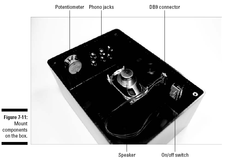
4. Secure the phono jacks and potentiometer with the nuts provided with each part.
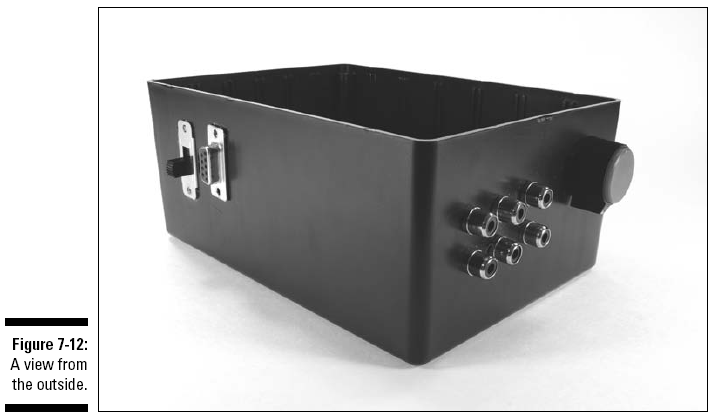
The outside of the box is shown in Figure 7-12. You can secure the speaker with four 1⁄2" 6-32 flathead screws and four 6-32 nuts. Use glue on the flanges of the DB9 connector and on the on/off switch to attach them to the box.
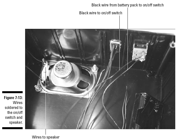
5. Solder the black wire from the battery pack to one lug of the on/off switch and solder an 8" black wire to the other lug of the on/off switch, as shown in Figure 7-13.
6. Solder a 6" black wire to each of the two solder lugs on the speaker, as shown in Figure 7-13.
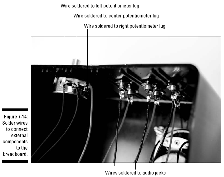
7. Solder an 8" wire to each of the three potentiometer lugs, as shown Figure 7-14.
8. Connect 8" wires to each of the audio jacks and solder them, as shown in Figure 7-14.
9. Use Velcro to attach the breadboard and the battery pack to the box.
10. Cut the wires from the phono jacks, potentiometer, on/off switch, battery pack, and DB9 connector to a length that allows you to arrange wires neatly in the enclosure.
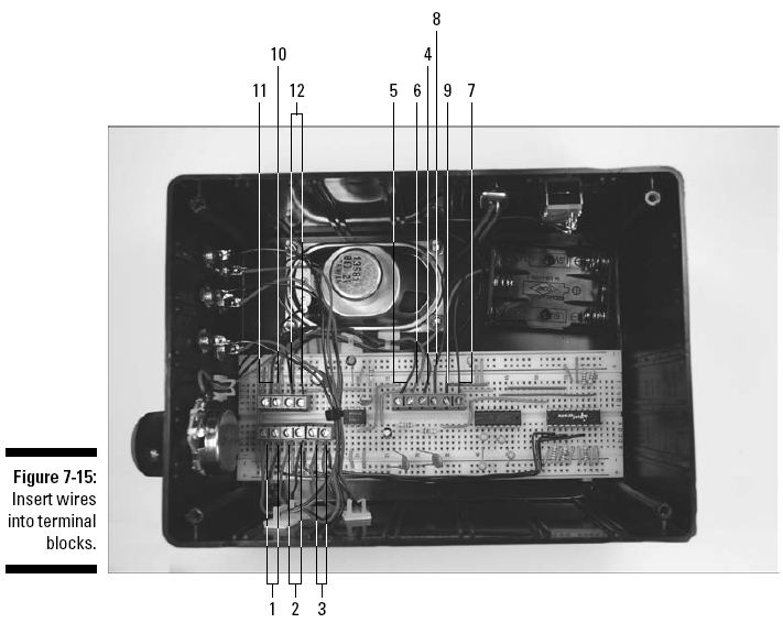
11. Strip insulation from the ends of cut the wires, insert them in the terminal blocks, and secure with wire clips, as shown in Figure 7-15.
The components shown in this figure, indicated by numbered callout, include1. Wires from left phono jack
2. Wires from center phono jack
3. Wires from right phono jack
4. Wire from left potentiometer lug
5. Wire from center potentiometer lug
6. Wire from right potentiometer lug
7. Wire from Pin 3 of DB9 connector
8. Wire from Pin 5 of DB9 connector
9. Wire from Pin 8 of DB9 connector
10. Red wire from battery pack
11. Black wire from on/off switch
12. Speaker wires
12. Place the on/off switch in the off position, insert batteries in the battery pack, and secure the lid on the enclosure with the screws provided.
13. Use your multimeter to find two contact pins on the tactile switches that are normally
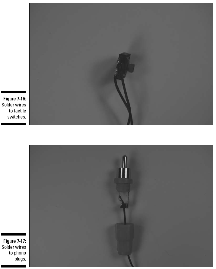
open (infinite resistance between the contact pins) and closed (nearly zero resistance between the two pins) when the switch is pressed.14. Solder a 12" wire to each of the two pins on each tactile switch, as shown in Figure 7-16.
15. Cut the wires from the tactile switches to the length you need to reach the jacks on the electronics enclosure after both the switches and the box are in place.
Leave about three extra inches of length to allow for some shifting as you stuff the box in the puppet.
16. Unscrew the top from each phono plug, slip the top over the wire, and solder each wire from the tactile switches to the center lug of a plug, as shown in Figure 7-17.
17. Screw the covers of the phono plugs back in place and feed each tactile switch to the proper location.
We placed one switch in each hand and a switch under the puppet’s nose.18. Feed the phono jacks behind the puppet, as shown in Figure 7-18.
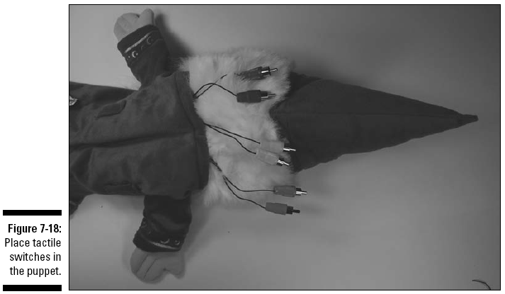
You might want to secure the switches in place in some fashion. We used a strip of adhesive-backed Velcro (somewhat wider than the switch) for the switch behind the nose. We stuck this to the back of the switch, put the switch in place, and pressed the adhesive back to the fabric, right under the puppet’s nose. Another idea is to use a few stitches of thread to stop the switch from moving.