

Murmuring Merlin
Creating Merlin’s circuit
Get your breadboard and other little parts ready to build the circuit that will help Merlin murmur. Here are the steps involved:
1. Place the SpeakJet IC (IC1), the MAX232 IC (IC2), the LM386 IC (IC3), and eight terminal blocks on a breadboard, as shown in Figure 7-5.
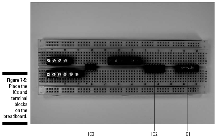
The eight terminal blocks shown in this figure will be used to connect two wires each to various components in the circuit. The wires from these terminal blocks go to the battery pack, the DB9 connector, the on/off switch, tactile switches in the puppet, the speaker, and the potentiometer, respectively.
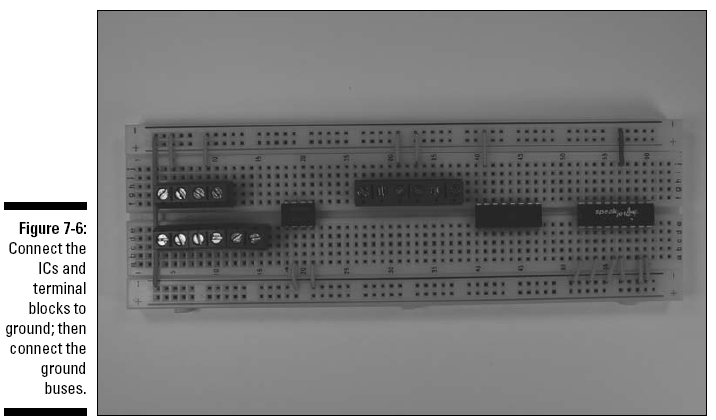
2. Insert wires to connect the ICs and the terminal blocks to the ground bus and then insert a wire between the two ground buses to connect them to each other, as shown in Figure 7-6.
Fourteen shorter wires connect components to ground bus; the long wire on the left connects the two ground buses.
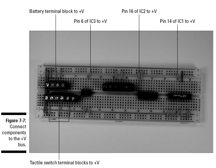
3. Insert wires to connect the ICs and the terminal blocks for the battery pack and the three tactile switches (S1, S2, S3) to the +V bus, as shown in Figure 7-7.
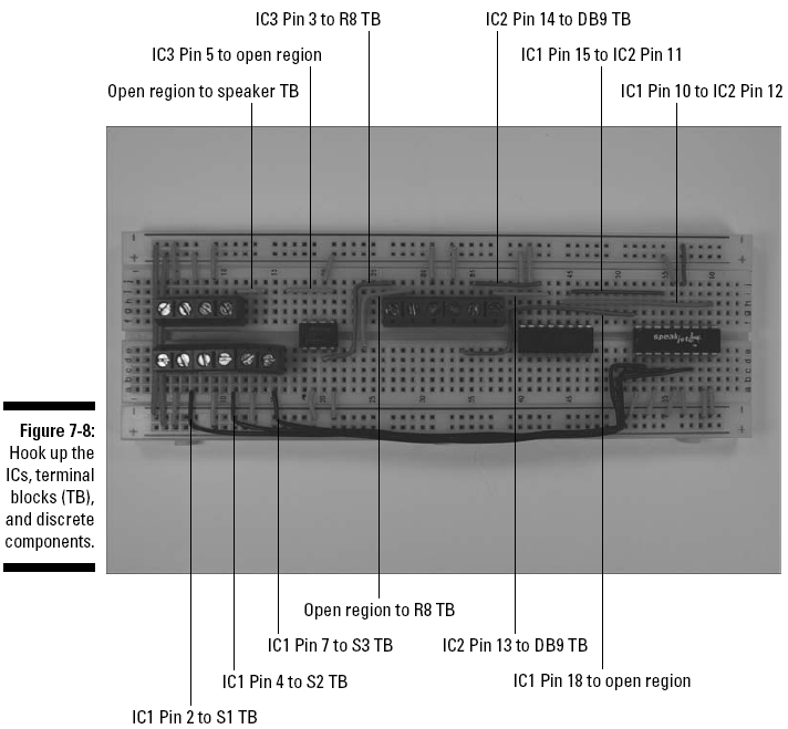
4. Insert wires to connect the ICs; terminal blocks for the potentiometer (R8) and tactile switches (S1, S2, S3); and discrete components, as shown in Figure 7-8.
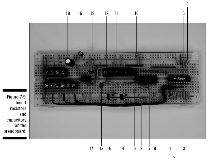
5. Insert discrete components on the breadboard, as shown in Figure 7-9.
When inserting electrolytic or tantalum capacitors, be sure to check the schematic to see where to insert the longer, positive (+) lead. The components shown in this figure, indicated by numbered callout, include
1. 1 kohm resistor R1 from IC1 Pin 2 to ground
2. 1 kohm resistor R2 from IC1 Pin 4 to ground
3. 1 kohm resistor R3 from IC1 Pin 7 to ground
4. 1 kohm resistor R4 from IC1 Pin 11 to +V
5. 1 kohm resistor R5 from IC1 Pin 12 to +V
6. 1 microfarad capacitor C2 from IC2 Pin 1 to Pin 3
7. 1 microfarad capacitor C3 from IC2 Pin 4 to Pin 5
8. 1 microfarad capacitor C4 from IC2 Pin 2 to ground
9. 1 microfarad capacitor C5 from IC2 Pin 6 to ground
10. 1 microfarad capacitor C1 from +V to ground
11. 33 kohm resistor R6 from wire to IC1 Pin 18 to an open region
12. 33 kohm resistor R7 from R6 to an open region
13. 10 microfarad capacitor C8 from R7 to wire to R8 terminal block
14. 0.01 microfarad capacitor C6 from R6 to ground
15. 0.01 microfarad capacitor C7 from R7 to ground
16. 10 microfarad capacitor C9 from IC3 Pin 7 to ground
17. 0.047 microfarad capacitor C10 from IC3 Pin 5 to open region
18. 10 ohm resistor R9 from C10 to ground
19. 100 microfarad capacitor C11 from wire to IC3 Pin5 to wire to speaker terminal block
We discuss in "Discovering Schematics" how you can determine how short to clip the leads of many of these components to make them fit neatly on the breadboard.
Make sure you wear your safety glasses when clipping leads!
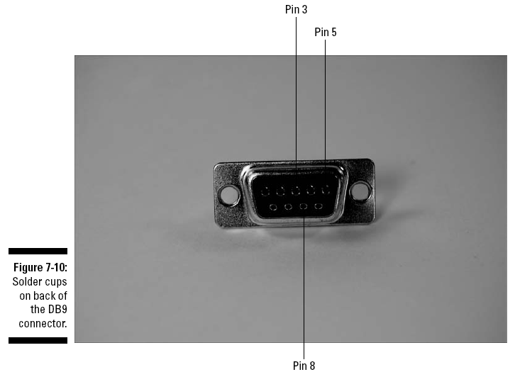
6. Solder 12" wires to the solder cups for Pins 3, 5, and 8 of the DB9 connector.
The location of these pins is shown in Figure 7-10. Although the manufacturer prints the pin numbers next to the solder cups, you might need a magnifying glass to read the pin numbers on the connector. Be sure to heed all the safety precautions about soldering that we list in "Discovering Schematics". For example, don’t leave your soldering iron on and unattended. And just in case a bit of solder has an air pocket and pops, wear your safety glasses!
7. Slip a 1" length of heat shrink tubing along each wire until it covers the soldered joints. Then heat the tubing with a hair dryer to secure it and protect the joints.