Building a radio circuit
The first step in building a radio is to tackle
the circuit that forms its electronic brains. Here are the steps
involved:
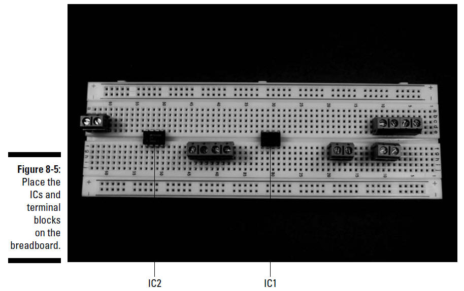
1. Place ZN416E (IC1), LM386N-1 (IC2), and seven
terminal blocks on the breadboard, as shown in Figure 8-5.
The seven terminal blocks shown in this figure will be
used to connect two wires each to various components in the
circuit. The wires from these terminal blocks go to the battery
pack for IC1, the battery pack for IC2, the on/off switch, the
coil, the variable capacitor, the speaker, and the
potentiometer.
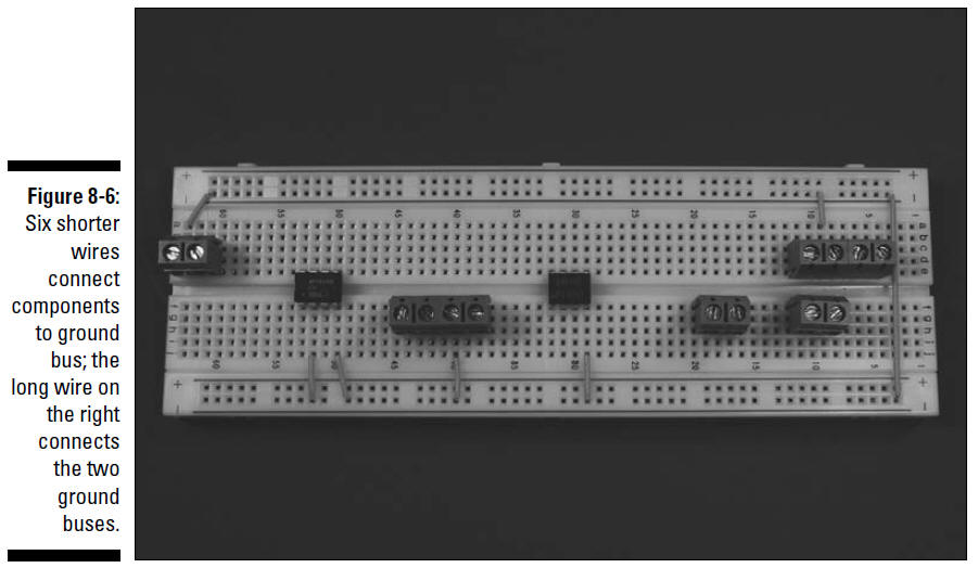
2. Insert wires to connect the ICs and the
terminal blocks to the ground bus and insert a wire between the
two ground buses to connect them to each other, as shown in
Figure 8-6.
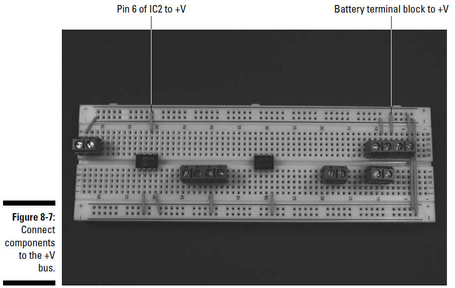
3. Insert wires to connect IC2 and the terminal
block for IC2’s battery pack to the +V bus, and a wire between
the two +V buses to connect them to each other, as shown in
Figure 8-7.
Do not connect IC1 to the +V bus.
If you do, you will
probably fry the poor IC because it
isn’t designed to take 6 volts.
4. Insert wires to connect the ICs, terminal
blocks for the coil (L1), variable capacitor (C2) and terminal
blocks for the potentiometer (R1), and terminal block for the
speaker and discrete components, as shown in Figure 8-8.
5. Insert two 0.047 microfarad capacitors (C4
and C9), two 10 microfarad capacitors (C6 and C7), one 100
microfarad capacitor (C8), two 0.001 microfarad capacitors (C1
and C3), one 0.1 microfarad capacitor (C5), and one 10 ohm
resistor (R2) on the breadboard, as shown in Figure 8-9.
When inserting
electrolytic capacitors, be sure to check the schematic
to see where to insert the longer, positive (+) lead.
We discuss in "Reading schematic" how you can
determine how short to clip the leads of many of these
components to make them fit neatly on the breadboard. Not to
sound like your mother, but make sure you wear your safety
glasses when clipping leads!