Scoping Out the Schematic
Imagine all that music and talk floating around
out there in the air. Time to get to work on a circuit that lets
you capture those sounds and pump them through a speaker. There
is only one breadboard to put together for this project. You can
see the schematic for the board in Figure 8-2.
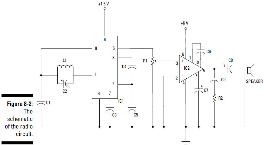
The following is a list of the schematic
elements for your radio:
L1 is a coil,
or inductor. You make this by wrapping wire around a ferrite
rod. This coil is both the antenna and half the tuning
circuit needed to tune the radio to
a particular station. The value of the inductor, given in
Henrys, is determined by the number of coils of wire you
wrap around the rod.
C2 is a
variable capacitor that forms a tuning circuit along with L1.
When you have a capacitor and
inductor in parallel, the value of the capacitor
and inductor determine the
resonance
frequency,
which is the frequency of the radio
station you tune in on your radio. As you change the value
of C2 by turning the knob connected to the capacitor, you
change the resonance frequency,
therefore tuning in to a different radio station.
IC1 is a ZN416E
integrated circuit that is designed to separate the voice
signal from the radio frequency carrier and amplify the
signal to a level sufficient to
power headphones.
C1 is a
capacitor that allows nonresonant radio frequency signals to
conduct to ground.
C3, C4, and C5
are suggested by the manufacturer of IC1; they shunt
high-frequency signals to ground, preventing them from
causing noise in certain parts of
the circuit inside of IC1.
IC2, an audio
amplifier named LM386N-1, takes the audio frequency electrical
signal generated by IC1 and amplifies it to provide sufficient
power to drive the speaker.
R1 is a
potentiometer that controls the sound volume.
C6 sets the
voltage gain of IC2 to 200. (Therefore, the voltage out will be
200 times the voltage in.)
C7 improves the
stability of the LM386 amplifier to prevent problems
such as oscillation, which can turn your signal into an
unintelligible garble of sound.
C8 removes any
DC offset from the output of the LM386 amplifier.
C9 acts as a
current bank for the output. This capacitor drains when
sudden surges of current occur and refills with electrons
when the demand for current is low.