Making a box into a radio
After you build the circuit, it needs a home, so
the next step in the process is to work with the box you
purchased for your radio enclosure.
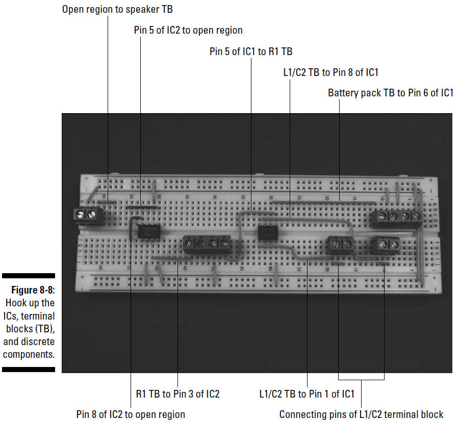
Follow these steps to get the box radio ready:
1. Drill holes in the box where you will mount
the variable capacitor, potentiometer, and on/off switch.
We put both the on/off switch on one side of the box and
the speaker, potentiometer and
variable capacitor on another side, but the placement
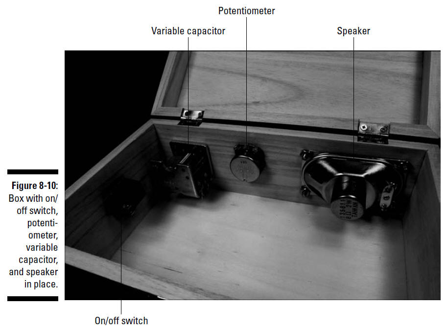
is really up to you. Figure 8-10 shows where we placed
these components.
2. Place the speaker against the face of the box
where you want to mount it and mark positions for the four
screws you’ll use to secure the speaker.
3. Drill holes to allow clearance for 6-32
screws.
We used a 9⁄64"
drill bit.
4. Draw an outline about
1⁄4"
smaller than the speaker shape for the opening
to let sound from the speaker out.
Use a coping saw to cut
the opening.
See Project Prep for more information about
choosing drill bit sizes for particular components and other
pieces of wisdom on how to customize a box for your projects.
Make sure you use safety glasses when drilling and clamp the box
to your worktable!
5. Slip the shaft of the on/off switch through
the drilled hole and secure with the nut provided.
6. Slip the shaft of the potentiometer through
the drilled hole and secure with the nut provided.
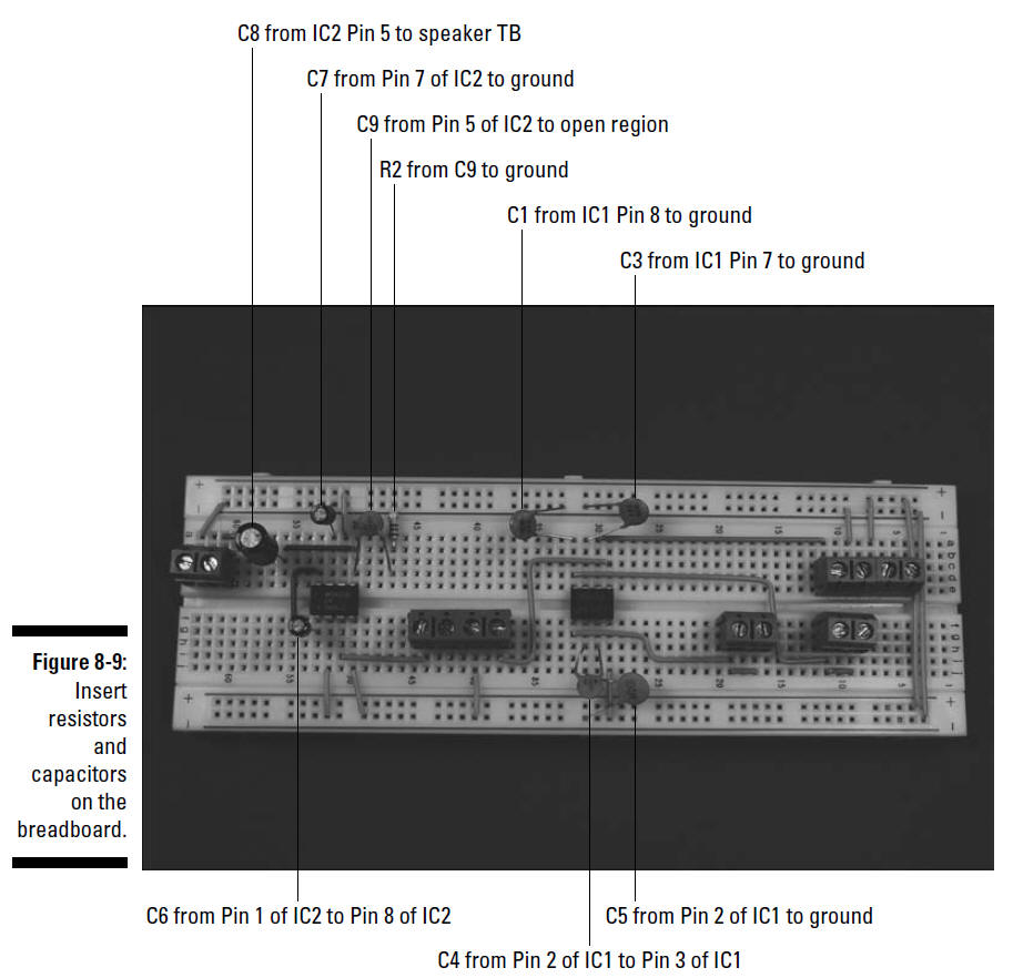
C8 from IC2 Pin 5 to speaker TB
C7 from Pin 7 of IC2 to ground
C9 from Pin 5 of IC2 to open region
R2 from C9 to ground
C1 from IC1 Pin 8 to ground
C3 from IC1 Pin 7 to ground
C6 from Pin 1 of IC2 to Pin 8 of IC2
C4 from Pin 2 of IC1 to Pin 3 of IC1
C5 from Pin 2 of IC1 to ground
7. Slip the knob on the potentiometer shaft and
secure with the set screw provided.
The tread on potentiometers is about
1⁄4"
long, so if the wall of your wooden
box is 1⁄4"
thick, you won’t be able to use the nut to secure the
potentiometer. Instead, glue the face of the
potentiometer to the box, making sure that you don’t get any
glue on the rotating shaft of the
potentiometer.
8. Slip the shaft of the variable capacitor
through the drilled hole and glue the metal body of the
capacitor to the wooden box.
Make sure you don’t get any glue on the shaft or other
moving parts of the capacitor.
9. Slip the knob on the variable capacitor shaft
and secure with the set screw provided.
10. Secure the speaker with four 6-32 flathead
screws and four 6-32 nuts.
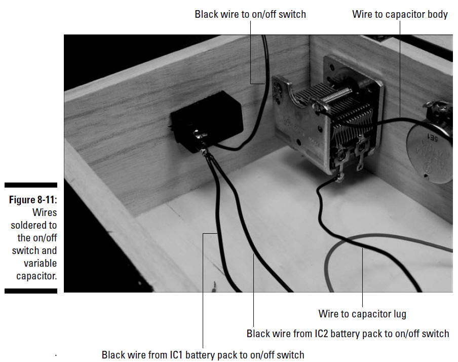
11. Solder the black wire from each of the
battery packs to one lug of the on/off switch and solder an 8"
black wire to the remaining lug of the on/off switch, as shown
in Figure 8-11.
12. Solder one 8" wire to a variable capacitor
lug and solder one 8" wire to the metal body of the variable
capacitor, as shown Figure 8-11.
The lugs are electrically connected to the stationary
plates of the capacitor, and the
metal body is electrically connected to the rotating plates.
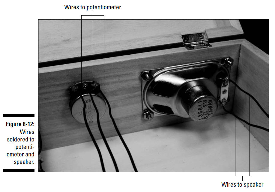
13. Solder 8" wires to each of the three
potentiometer lugs, as shown Figure 8-12.
14. Solder 8" wires to each of the two speaker lugs, as shown
Figure 8-12.
Be sure to heed all the safety precautions about
soldering that we give you in Chapter 2. For example, don’t
leave your soldering iron on and unattended. And just in case a
bit of solder has an air pocket and pops, wear your safety
glasses!