Making a talking pumpkin
This is the mouthpiece of the pumpkin
organization: the one that receives the IR beam and plays back
whatever you record. Follow these steps to build your talking
pumpkin:
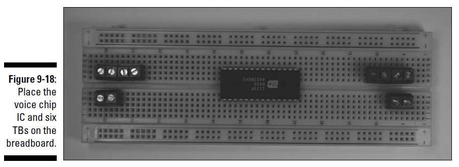
1. Place the voice chip IC and six terminal
blocks on the breadboard, as shown in Figure 9-18.
As you can see in this figure, you connect two
wires to each terminal block. The wires from these six terminal
blocks (TBs) go to the battery pack, on/off switch, record
switch, IR detector, speaker, and microphone, respectively.
2. Insert wires to connect each component and
terminal to the ground bus and insert a wire between the two
ground buses to connect them, as shown in Figure 9-19.
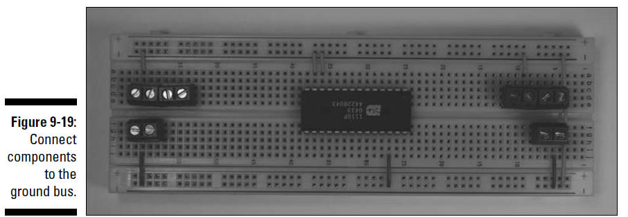
In this figure, seven shorter wires connect
components to ground bus (marked with a – on this breadboard);
the long wire on the right connects the two ground buses
together.
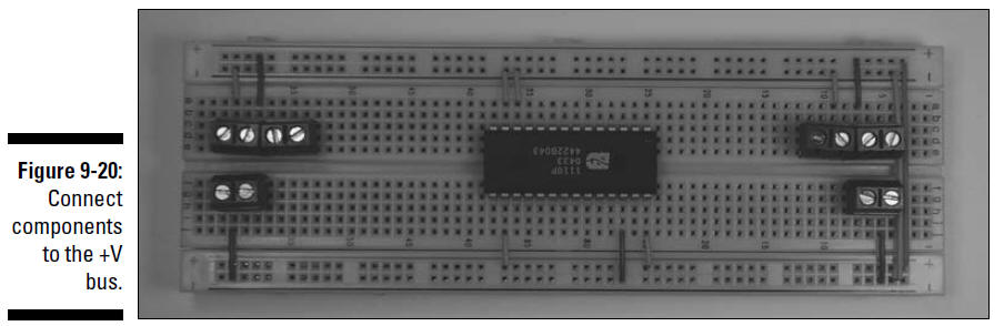
3. Insert wires to connect each component and
terminal to the +V bus and insert a wire between the two +V
buses to connect them, as shown in Figure 9-20.
In this figure, five wires have been added: four
shorter wires connect components to the +V bus (marked with a +
on this breadboard); the long wire on the right connects the two
+V buses.
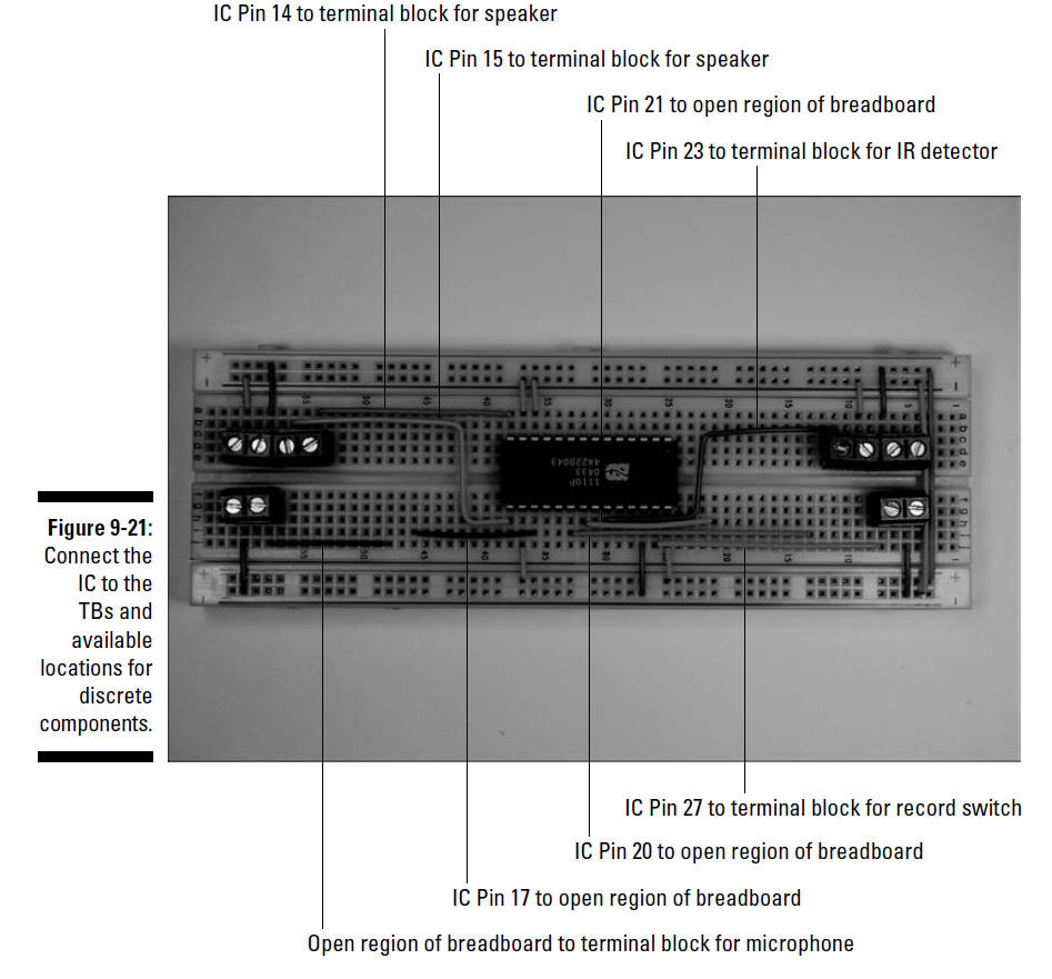
4. Insert wires to connect the voice chip IC
to the terminal blocks and to the open regions of the breadboard
where discrete components will be inserted, as shown in Figure
9-21.
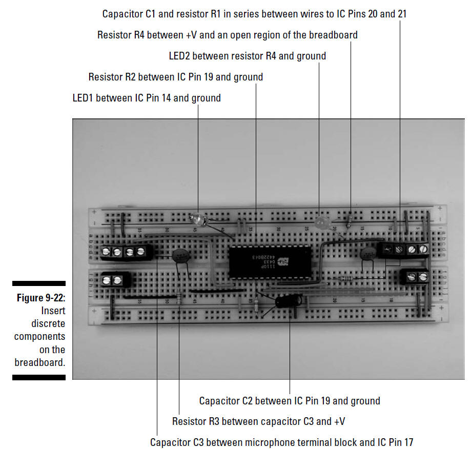
5. Insert discrete components on the
breadboard, as shown in Figure 9-22.
The short lead of the LEDs and C2 go to the ground bus.
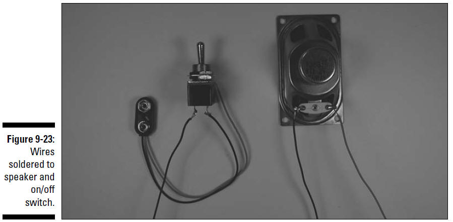
6. Connect 6" wires (any color will work just
fine) to the speaker and solder them, as shown in Figure 9-23.
7. Connect the black wire from the battery
pack snap and another 6" black wire to the on/off switch and
solder them together, as shown in Figure 9-23.
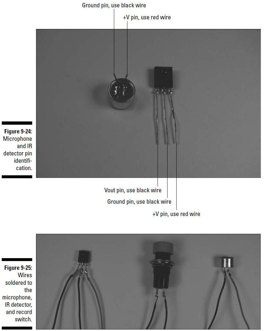
8. Connect a 6" red wire and a 6" black wire
to the microphone pins, as indicated in Figure 9-24. Then solder
them, as shown in upcoming Figure 9-25.
9. Connect a 6" red wire and two 6" black
wires to the IR detector pins, as indicated in Figure 9-24; then
solder them, as shown in upcoming Figure 9-25.
10. Connect two 10" wires (any color works)
to the record switch and solder them, as shown in Figure 9-25.
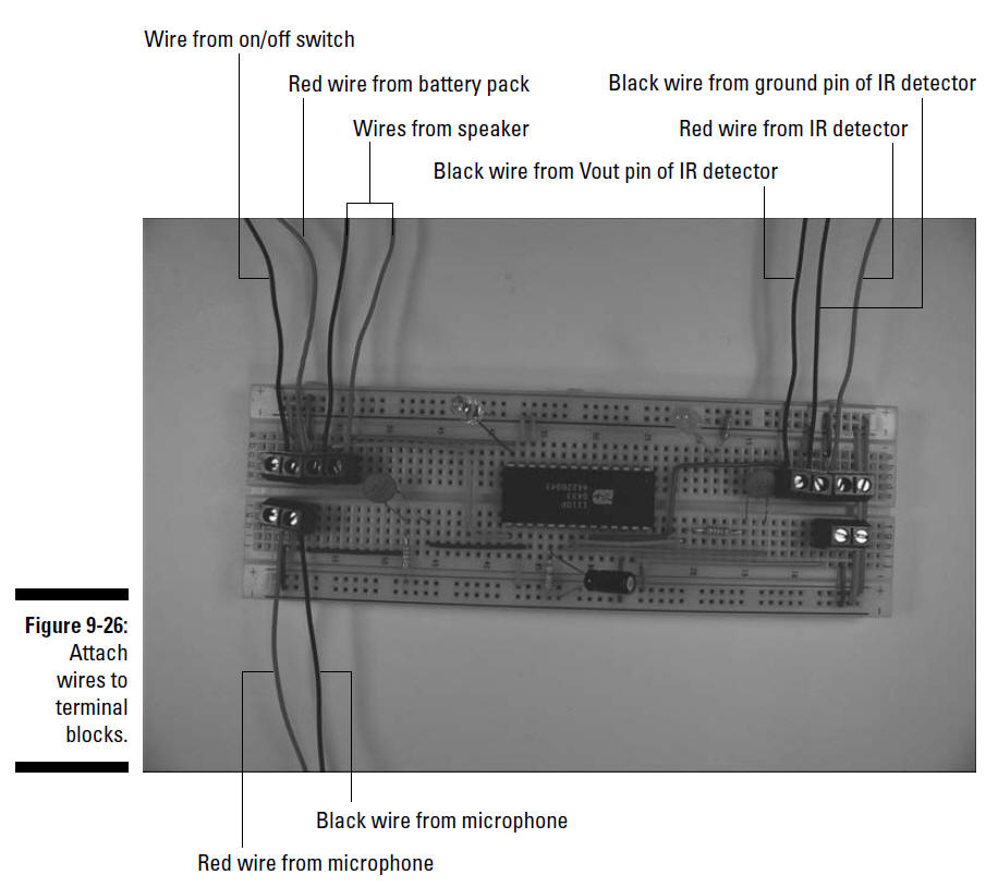
11. Attach the wires from the battery pack
snap connector, on/off switch, IR detector, microphone, and
speaker to the terminal blocks, as shown in Figure 9-26.
When attaching the wires to the terminal
blocks, cut the wires to the length you need and strip the ends.
12. Use your handy mini hacksaw or a utility
knife to shape foam blocks to fit inside the bottom of the
pumpkin.
13. On the side of the plastic pumpkin that will
be out of sight, cut holes just large enough to allow the shaft
of the on/off switch, microphone, and record switch to pass
through.
14. On the side of the talking pumpkin that will
face the silent pumpkin, cut a slot just large enough to allow
the IR detector to fit through.
15. Place the breadboard and speaker on the
foam. Then slip the on/off switch, microphone, and IR detector
through the holes you cut, as shown in Figure 9-27.
Figure 9-28 shows the IR detector protruding
from the side of the pumpkin.
16. Tuck the wires off to the side; refer to
Figure 9-27.
You can secure the on/off switch with the nut
supplied and use either a press fit or a bit of glue to hold the
microphone and IR detector in place.
17. Slip the record switch through the hole you
cut for it and secure it with the supplied nut; refer to Figure
9-27.
The direction of the threads on the body of the
switch determines which way you insert it. The one we used had
threads positioned such that the nut would be attached from
inside the pumpkin, as shown from the outside in Figure 9-29.
18. Insert the wires from the record switch to
the remaining terminal block on the breadboard
19. Make sure that the on/off switch is in the
off position and attach the battery snap connector to a filled
battery pack.
20. Place the battery pack in the pumpkin.
Your pumpkins are all ready to scare the pants
off of your Halloween visitors.
The completed talking pumpkin is shown in Figure 9-30.