Scoping out the schematic
You put together two breadboards for this
project: one that transmits and one that receives and sounds
off. First, you can see the schematic for the board that goes in
what we call the
silent pumpkin
(the one with the
transmitter in it) in Figure 9-3.
Here’s the nitty-gritty of the schematic
elements for the silent pumpkin:
The
IR LED (LED2)
is one of the
key components of this circuit; the purpose
of the rest of the circuit is to send an electrical
current, which turns on and off at
a frequency of 38 kHz, through this LED. This current
causes the LED to transmit IR light that turns on and off
at a frequency of 38 kHz (38,000
times a second: so fast you can’t even see a flicker).
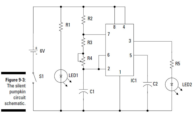
IC1
is the other key component
of this circuit. This is an LM555 timer
chip that you use to generate a square wave at its output
on Pin 3.
R2, R3, R4, and C1
are three resistors and a
capacitor, respectively, that form
the RC circuit that determines the frequency of the square wave
generated by the LM555 timer chip.
S1 is an SPST
(single-pole, single-throw; see Chapter 4) toggle switch
connected between the negative pole of the battery pack
and the breadboard ground bus. When
this switch is open, no current can flow, and so
the circuit turns off. When this switch is closed, the
circuit turns on.
LED2 provides a
light (we use a yellow light) to simulate a candle’s glow
in the pumpkin. This LED is on whenever S1 is closed.
R1 is a
resistor that limits the current running through LED1 to
approximately 20 milliamps (mA).
R5 is a
resistor that limits the current running through LED2 to
approximately 30 milliamps (mA).
C2 is a
capacitor that reduces the occurrence of noise on Pin 5, which
could cause false triggering of the IC. This might occur
if Pin 5 were left unconnected.
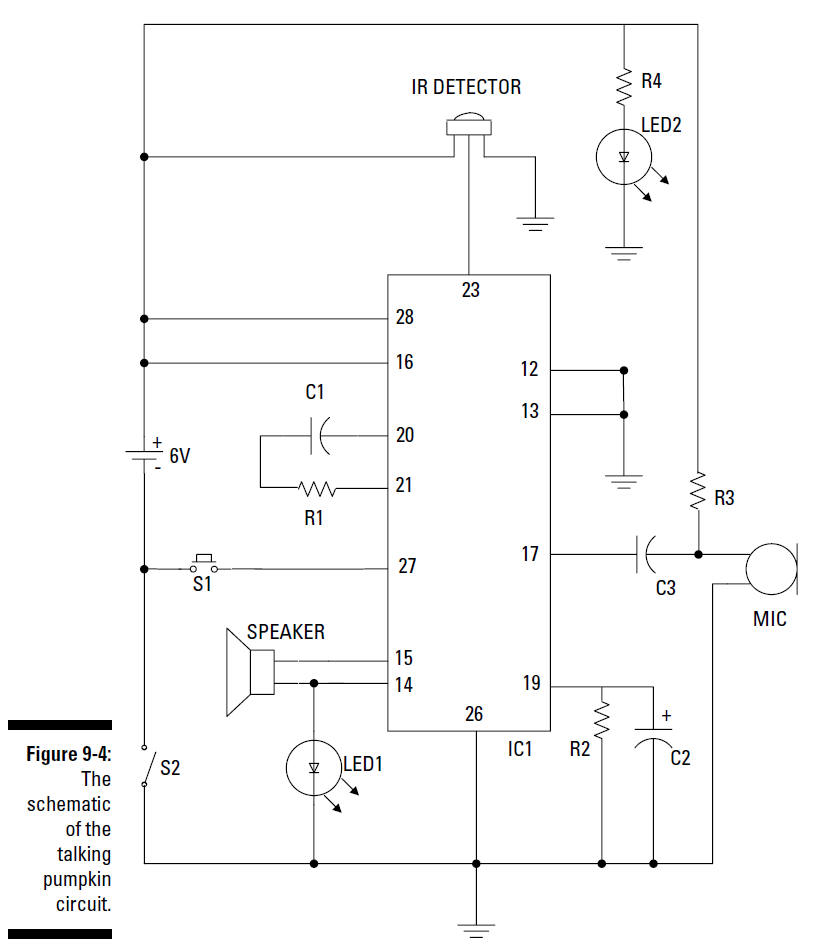
Now it’s time to run down the elements of the
receiver schematic that goes into the talking pumpkin. Take a
look at the schematic in Figure 9-4.
Time, time, timers
When you connect a 555 timer IC to resistors and
capacitors in the arrangement shown in the schematic, the timer
IC generates a digital waveform from its output. The frequency
of the waveform is determined by how fast the capacitor fills
and drains. You calculate how fast the capacitor fills to
two-thirds of its capacity or drains to one-third of its
capacity by using the RC time constant equation. (This involves
math, so it’s not for the faint of heart.) The RC time constant
for filling the capacitor is T1 = (R2 + R3 + R4)
×
C
The RC time constant for draining the capacitor is
T2 = (R3 + R4) ×
C
In this circuit, R2, R3, and R4 determine how fast the
capacitor charges and discharges. The extent
to which the capacitor is filled determines the voltage
on Pins 2 and 6 and the voltage applied to
the circuit inside the IC. When the voltage reaches
two-thirds of +V, the circuitry connected to Pin
6 turns on and causes the output to change from +V to 0
(zero) volts. It also causes the charge on
the capacitor to drain through Pin 7 to ground. As the
capacitor drains, the voltage to Pins 2 and
6 drops. When the voltage gets to one-third of the +V,
the circuitry connected to Pin 2 turns on and
causes the output of the IC to shift from 0 (zero) to +V
and disconnects Pin 7 from ground, which
allows the capacitor to charge back up to two-thirds of
+V. At this point, the cycle starts again.
The
IR detector
is the key component of
this circuit. It contains a photodiode
that detects infrared light and an integrated circuit
that produces either +V or 0 volts
on its output pin. Exactly what volts the IR detector
produces depends on whether it detects a 38 kHz infrared
signal (resulting in 0 volts
output) or not (resulting in +V output).
IC1 is the
other key component of this circuit. This is a chip that you
can use to record a sound or voice message and play it
back. We connect the output of the
IR detector to Pin 23 of IC1. Voltage on Pin 23
starts a playback when the voltage changes from +V to 0
volts. Here’s how this works: When
a person walks between the pumpkins, the voltage
from the IR detector changes from 0 volts to +V. When the
person leaves the beam field, it
drops back down to 0 volts. The jump back to 0
volts is the point when your recording starts to play.
The
speaker
is connected to
Pins 14 and 15 of IC1. The speaker plays
messages that you recorded on IC1. You connect
LED1
between Pin 14 of IC1 and
ground. When your message plays,
this LED generates a flickering light. (We used a red LED to
get a red light.)
For a brighter light, try using an LED with a
clear glass shell instead of a translucent shell.
LED2 provides a
steady light. We chose yellow, as
if you had a candle in the pumpkin.
R4 is a
resistor that limits the current running through LED2 to
approximately 20 milliamps.
S1
is a normally open (NO)
pushbutton switch that when depressed,
connects Pin 27 of IC1 to ground. This is how you record
sounds to
IC1 through the microphone. Recording stops when
you release the S1 pushbutton.
R3 is a
resistor that connects the microphone to +V, supplying the 4.5
volts that the microphone needs to function.
C3 is a
capacitor that removes the DC voltage from the AC signal that’s
flowing from the microphone to Pin 17 of IC1.
S2 is the
on/off switch between the negative terminal of the battery pack
and the ground bus of the circuit board.
R1 and
C1
filter out that pesky
electrical noise.
R2 and
C2
connect the automatic gain
control circuit inside IC1 to
ground. The values of R2 and C2 determine how fast the automatic
gain control responds to changes in
volume when you’re recording a message.