Making a silent pumpkin
Tackle the silent partner of this pumpkin duo
first. Here are the steps
involved:
1. Place the LM555 IC and three terminal blocks
on a breadboard, as
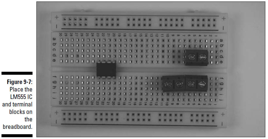
The three terminal blocks shown in this figure
will be used to connect two wires each to various components in
the circuit. The wires from these terminal blocks go to the
battery pack, IR LED, and potentiometer, respectively.
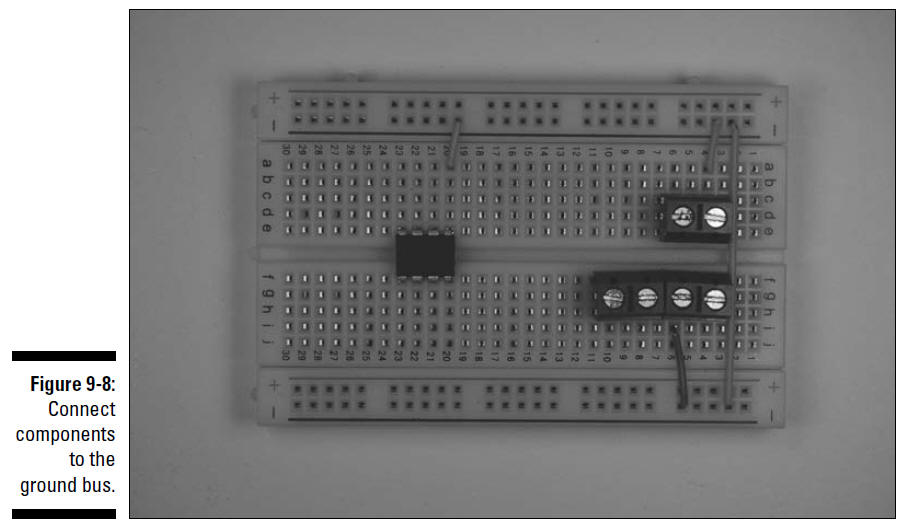
2. Insert wires to connect the IC and the
terminal blocks to the ground bus (marked with a – sign on this
breadboard) and insert a wire between the two ground buses to
connect them to each other, as shown in Figure 9-8.
Three shorter wires connect components to the
ground bus; the long wire on the right connects the two ground
buses.
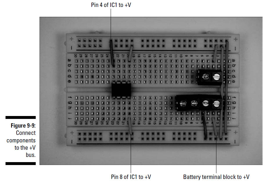
3. Insert wires to connect the IC and the
terminal block for the battery to the +V bus, as shown in Figure
9-9.
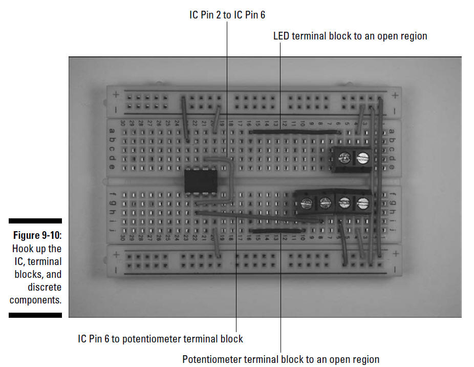
4. Insert wires to connect the IC, terminal
blocks, and discrete components, as shown in Figure 9-10.
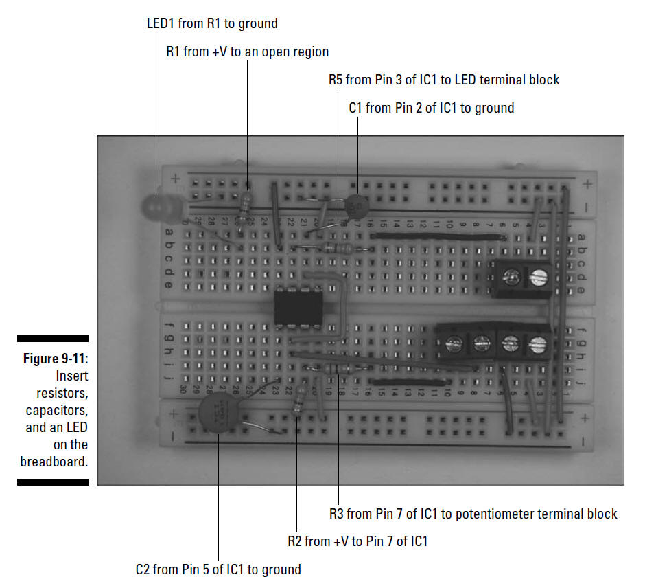
5. Insert discrete components on the breadboard,
as shown in Figure 9-11.
Note that the shorter of the LED leads is
inserted in the ground bus.
6. Solder the black wire from a battery snap to
one lug of the on/off switch and solder a 5" black wire to the
other lug of the on/off switch.
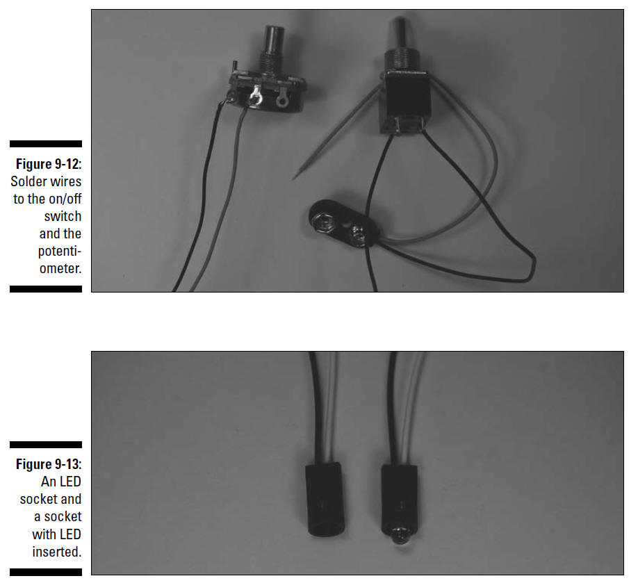
7. Solder two 5" wires to the potentiometer, as
shown Figure 9-12.
Be
sure to heed all the safety precautions about soldering that we
give you in Chapter 2. For example, don’t leave your soldering
iron on and unattended. And just in case a bit of solder has an
air pocket and pops, wear your safety glasses!
8. Cut the leads of the IR LED to
1⁄4",
keeping track of which is the long (+V) lead.
Wear your safety glasses any time you cut wires!
9. Insert the IR LED in the LED socket, making
sure that the +V lead is lined up with the white wire from the
socket.
Figure 9-13 shows the LED inserted into the socket.
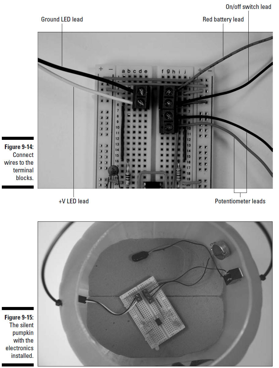
10. Attach wires from the LED, battery pack
snap, on/off switch, and potentiometer to the terminal blocks,
as shown in Figure 9-14.
11. Use a mini hacksaw or a utility knife to
shape foam blocks so that they fit inside the bottom of the
pumpkin, as shown in Figure 9-15.
We used the type of foam used to hold dried
flower arrangements. You could also use packing foam.
12. On the side of the plastic pumpkin that will
face the talking pumpkin, cut a hole just large enough to allow
the LED socket to fit.
13. On the side of the plastic pumpkin that will
face away from visitors, cut holes just large enough to allow
the shaft of the on/off switch and potentiometer to pass
through.
Be sure to wear safety glasses in case a piece
of plastic flies off in the wrong direction!
14. Attach the battery snap connector to the
battery pack and place the breadboard in the pumpkin.
Because this pumpkin probably won’t move around
much, we just chose to lay the breadboard on the foam, as shown
in Figure 9-15.
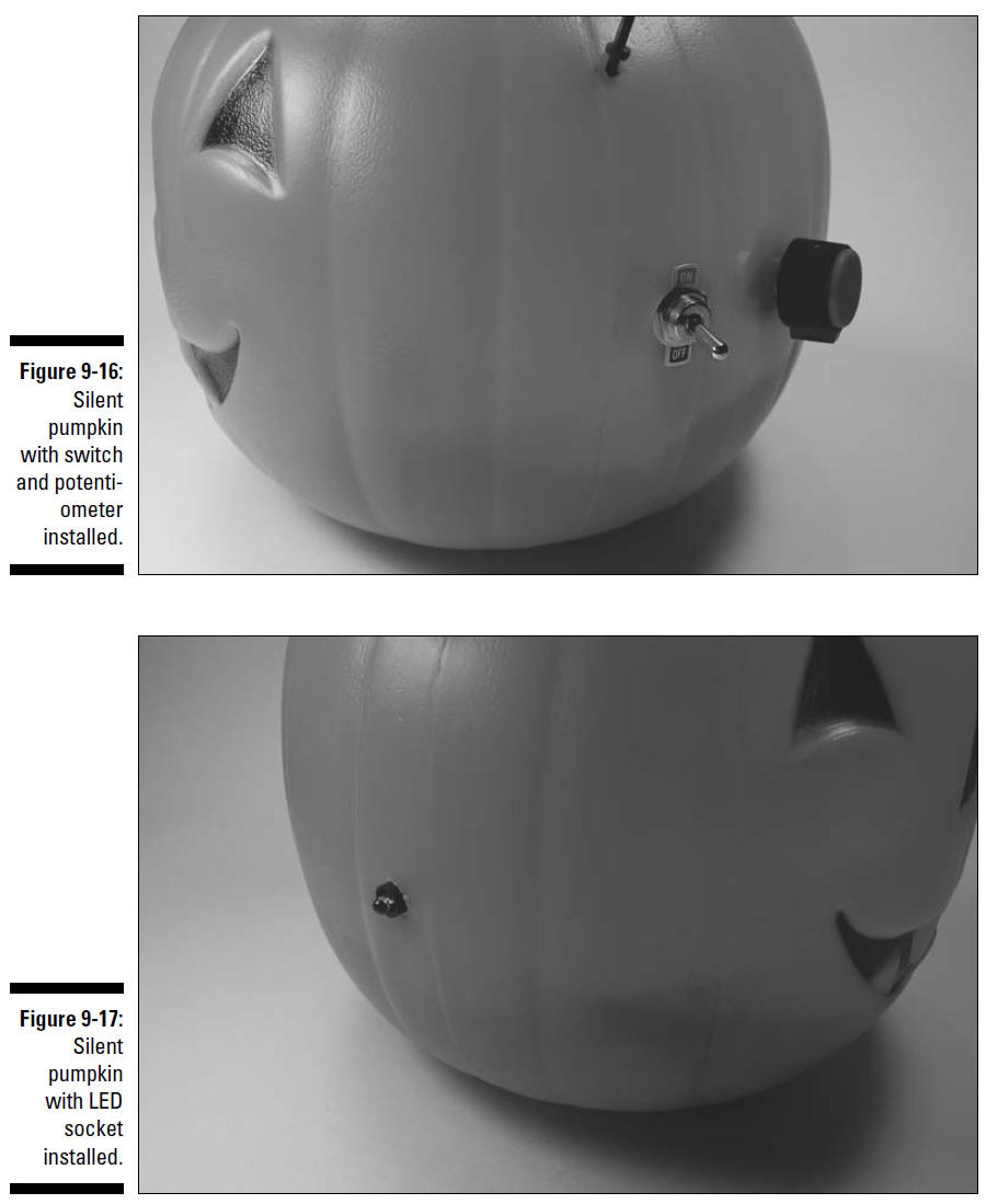
15. Slip the on/off switch and the potentiometer
through the holes you cut for them and use the nuts supplied
with them to secure them, as shown in Figure 9-16.
16. Slip the LED socket through the hole you cut
for it.
Figure 9-17 shows the LED socket installed in the pumpkin.
If the hole for the LED socket is small enough
that the socket fits tightly, this “press fit” will hold it in
place; if the socket is a little loose, use a little glue to
secure it to the pumpkin. Read about what kind of glue to use in
Chapter 3.
17. Make sure that the on/off switch is in the
off position and then attach the battery snap connector to a
filled battery pack.
18. Place the battery pack in the pumpkin.