Making the transmitter
The transmitter — the thing that you hold in
your hand like a TV remote control — is what you aim at the
go-kart to control it. Follow these steps to build the
transmitter circuit:
1. Place the encoder IC, resonator, voltage
regulator, resistor, and capacitor on the breadboard, as shown
in Figure 11-7.
Make sure you put the negative lead of the
capacitor in the same breadboard row as the center pin of the
voltage regulator and the positive lead in the same breadboard
row as the +5 volt output pin of the regulator.
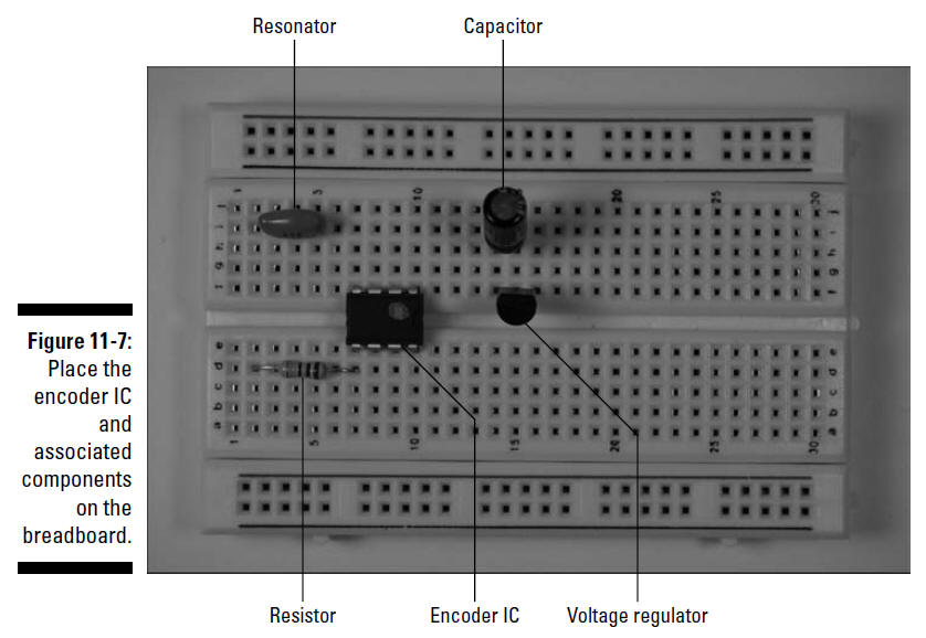
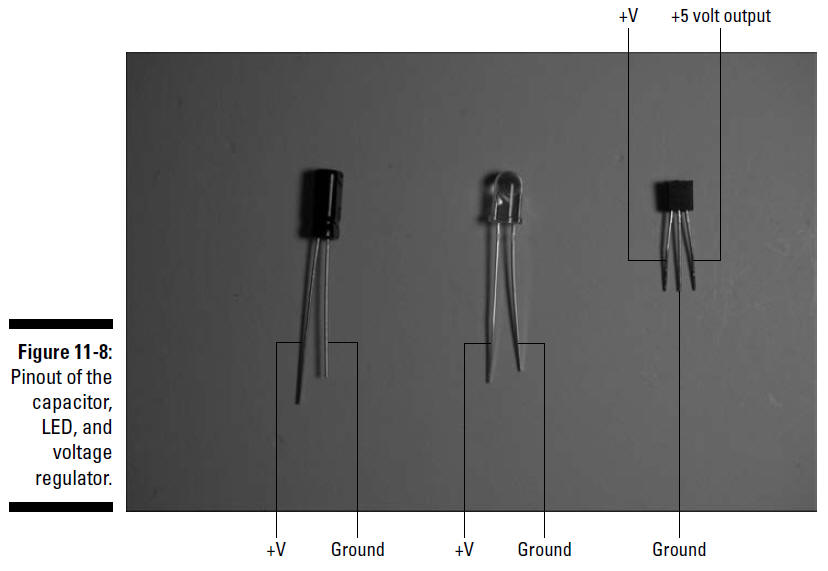
Figure 11-8 shows the uses of each pin of the
voltage regulator, capacitor, and LED.
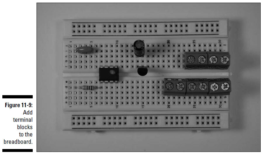
2. Place five terminal blocks on the breadboard,
as shown in Figure 11-9.
The five terminal bocks shown in this figure
will be used to connect two wires each to various components in
the circuit. The wires go to the battery pack, IR LED, on/off
switch, motor R switch, and motor L switch, respectively.
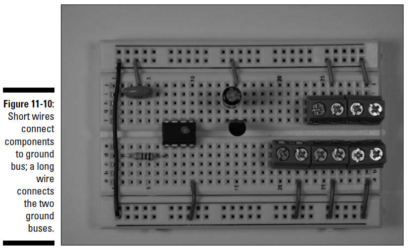
3. Insert wires to connect each component and
terminal to the ground bus and insert a wire between the two
ground buses to connect them, as shown in Figure 11-10.
On the resonator, the center of the three leads
is the ground lead. Eight shorter wires connect components to
ground bus; the long wire on the left connects the two ground
buses.
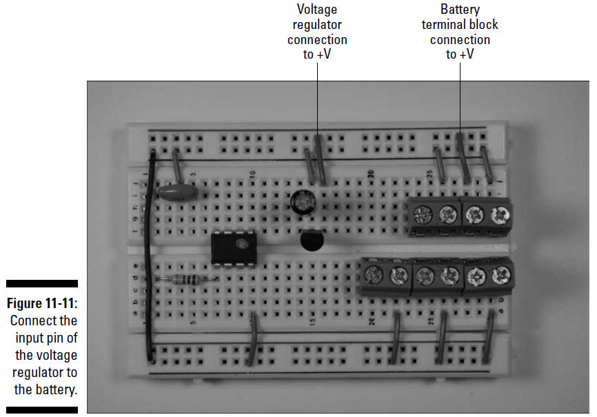
4. Insert wires to connect the input pin of the
voltage regulator and the terminal block for the battery to the
+ voltage bus, as shown in Figure 11-11.
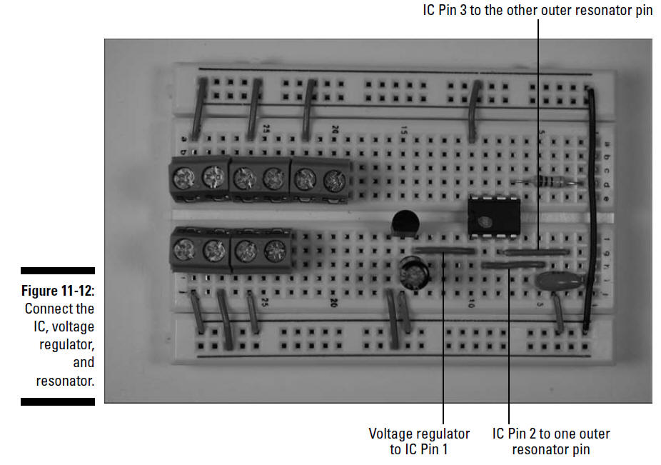
5. Insert wires to connect the encoder IC,
voltage regulator, and resonator, as shown in Figure 11-12.
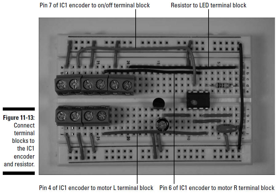
6. Insert wires to connect the terminal blocks
to the IC1 encoder and resistor, as shown in Figure 11-13.
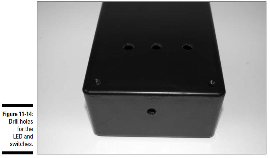
7. Drill holes in the transmitter box for the
LED and switches.
Figure 11-14 shows holes drilled in the front of the box
for the LED and in the top of the
box for the switches. The size of drill bit that you use
depends upon the diameter of the switches and LED socket
you use. We used a
1⁄4"
drill bit to drill the hole for the LED and a
5⁄16"
drill bit to drill the holes for
the switches.
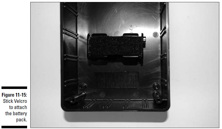
8. Place adhesive-backed Velcro in the box and
on the battery pack, as shown in Figure 11-15.
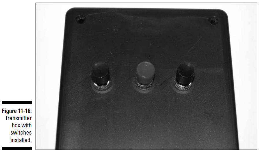
9. Place the three switches through the holes,
as shown in Figure 11-16, and secure them to the box with the
nuts included with the switches.
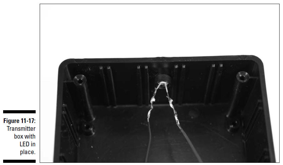
10. Feed the LED socket through the hole in the
front of the box. Slip the LED into the socket from the inside
of the box, and then slip the bottom half of the socket over the
leads and tighten to secure the LED.
11. Connect one black and one red 6" wire to the
LED and solder them.
The secured and soldered LED is shown in Figure 11-17.
The red wire must be connected to the longer of
the LED leads. After the wires have cooled, wrap them in
electrical tape to prevent the leads from shorting.
Heed all the safety precautions about soldering
that we talk about in Chapter 2. For example, don’t leave your
soldering iron on and unattended. And for heaven sakes — don’t
drop it in your lap when it’s hot!
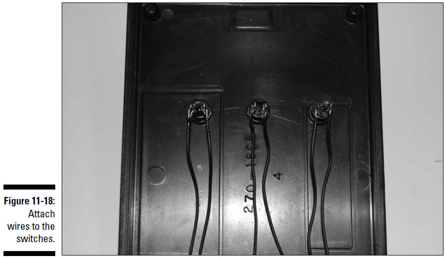
12. Connect 6" wires (any color is okay) to the
switches and solder them, as shown in Figure 11-18.
To connect wires to the switches, feed the wire
through the lug and twist to secure it.
13. Secure the breadboard in the box with
Velcro. Or, if the breadboard already has adhesive tape on the
back like the one we used, just use the tape.
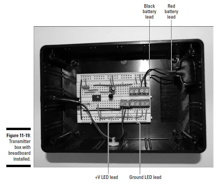
14. Attach the wires from the battery pack snap
connector and the LED to the terminal blocks, as shown in Figure
11-19.
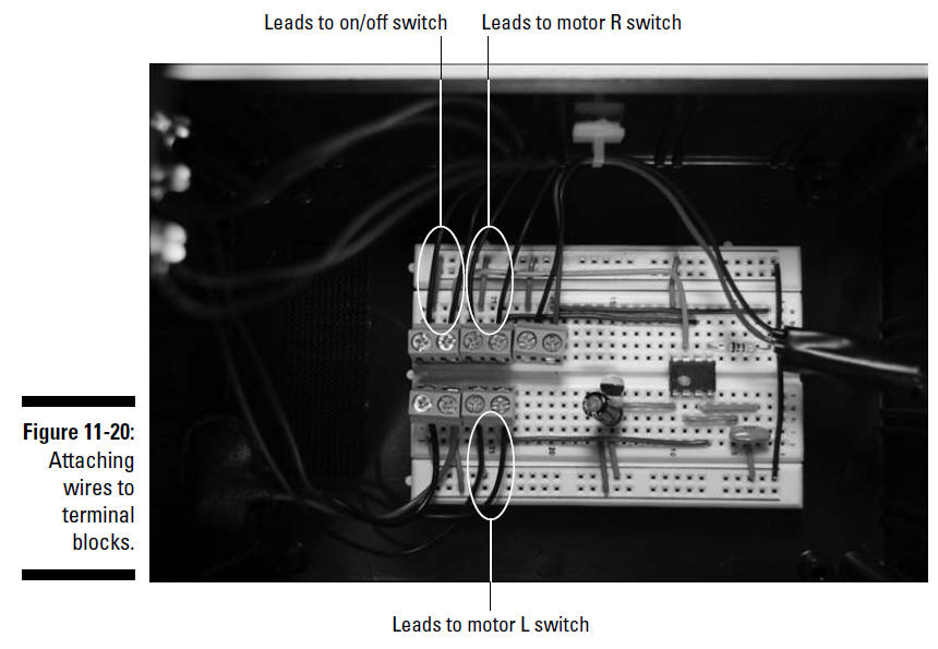
15. Attach the wires from the switches to the
terminal blocks, as shown in Figure 11-20.
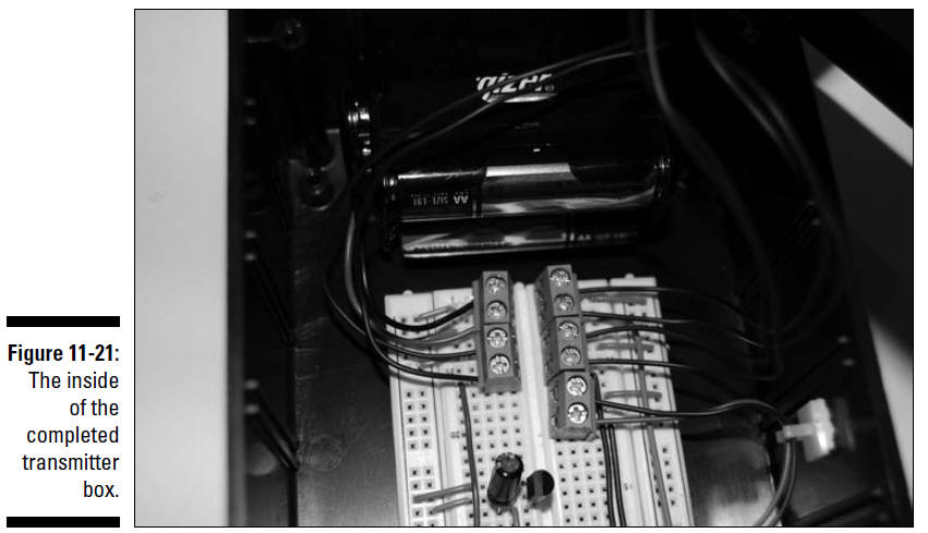
16. Place batteries in the battery holder,
connect the snap, and secure the holder in the box with Velcro,
as shown in Figure 11-21.
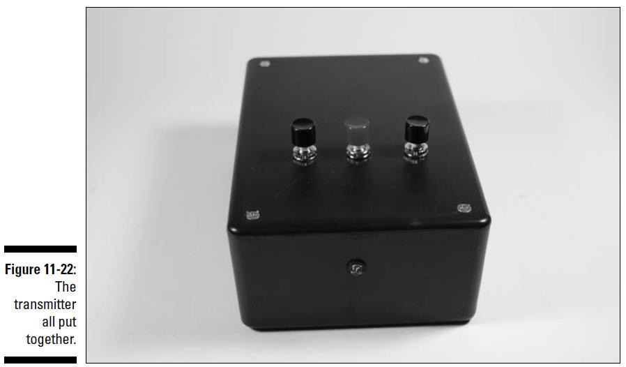
17. Attach the cover to the box with the
included screws.
The completed box is shown in Figure 11-22.