Making the receiver circuit board
The receiver, quite logically, receives the
signal sent by the transmitter. You will eventually affix the
receiver circuit to the body of the go-kart, but don’t put the
kart before the horse (so to speak): Before you affix the
receiver, you have to build it.
To build the receiver circuit, follow these
steps:
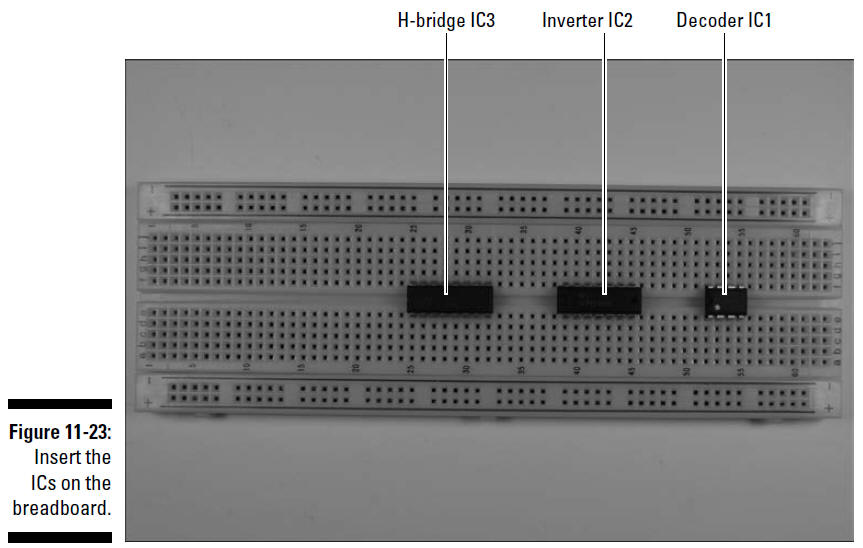
1. Insert the ICs on the breadboard, as shown in
Figure 11-23.
Be sure to leave room between each IC to place
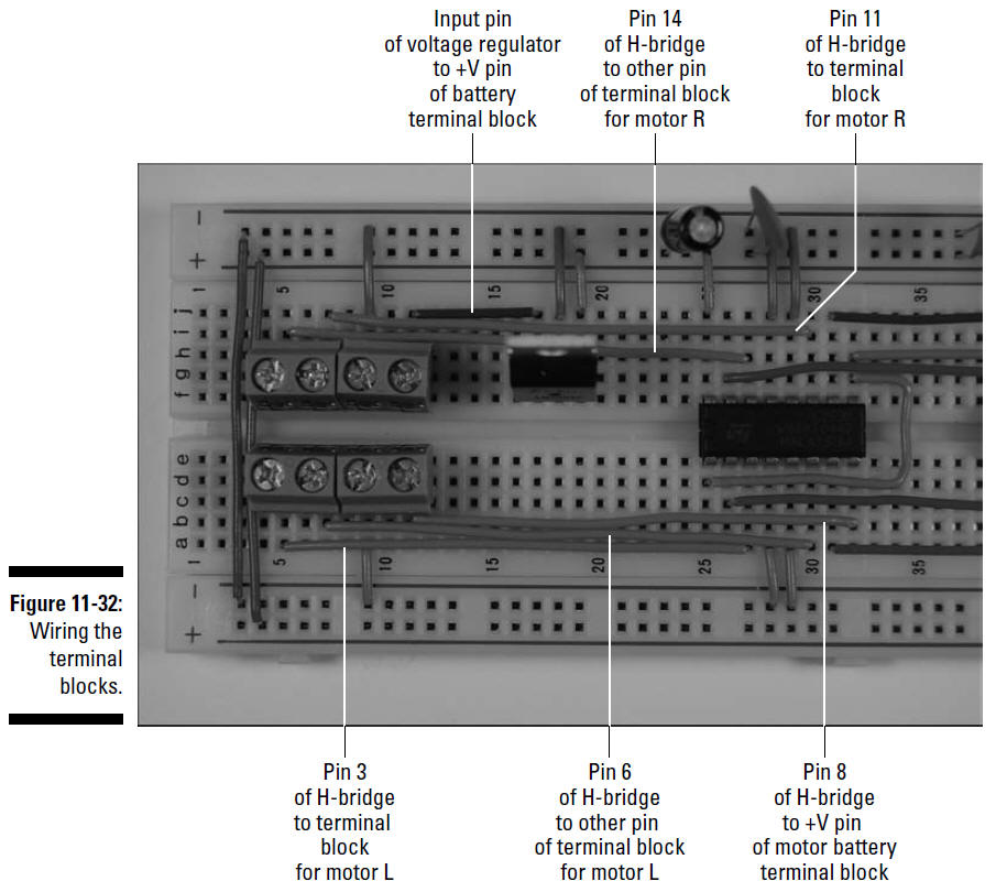
wires (as shown in the final figure in this section, the
upcoming Figure 11-32). Also, leave room at the end of the board
near the decoder to insert the IR detector and the resonator.
Finally, leave room at the end of the board near the Hbridge to
add terminal blocks
2. Insert the voltage regulator, resonator, and
IR detector on the breadboard, as shown in Figure 11-24.
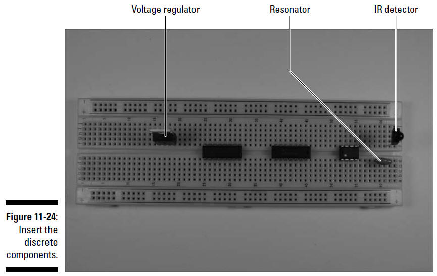
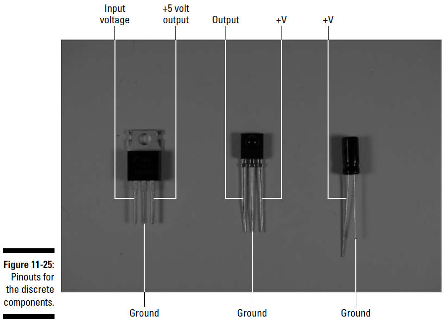
Figure 11-25 shows how the circuit uses each pin
of the voltage regulator and IR detector (referred to as
discrete
components).
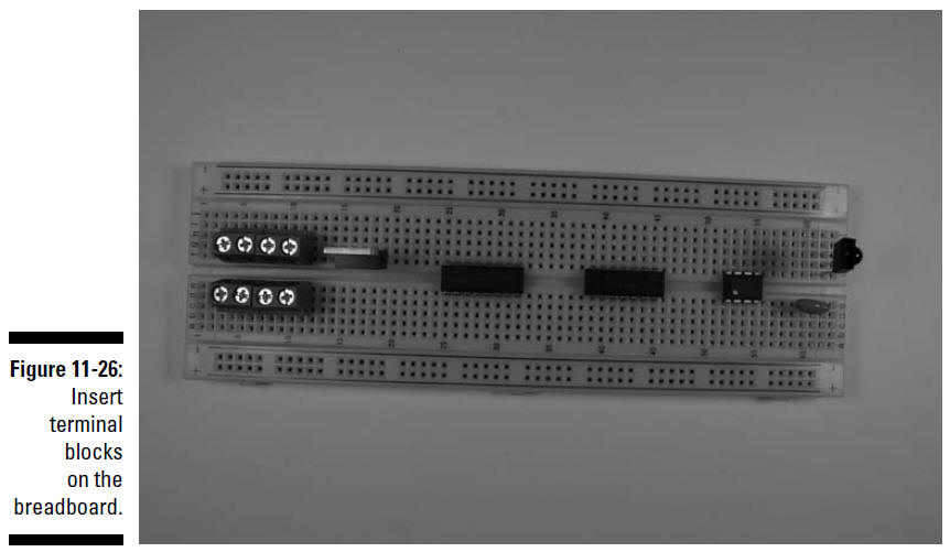
3. Insert four terminal blocks a few rows in
from the end of the breadboard, as shown in Figure 11-26.
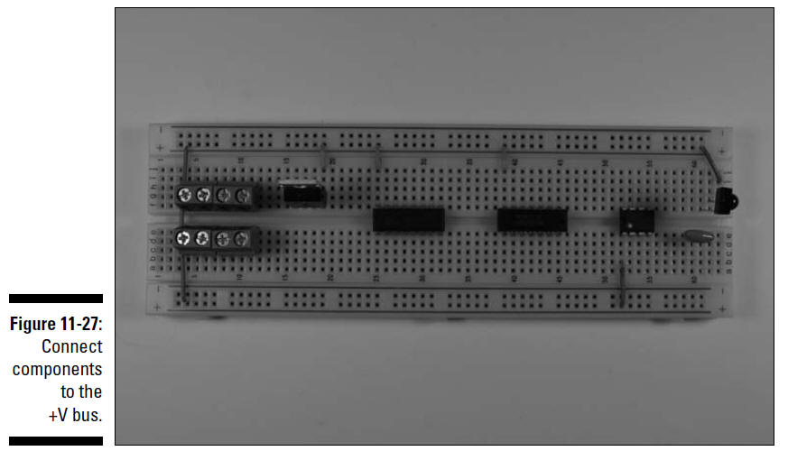
4. Insert wires to connect each component to the
+ voltage bus and a wire to connect the two + voltage buses, as
shown in Figure 11-27.
Note that you connect the +5 volt output of the
voltage regulator to the + voltage bus because the voltage
regulator takes the approximately +6 volts from the battery and
changes it to +5 volts. It then supplies those +5 volts to the +
voltage bus so that it can be used by the other components.
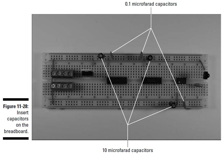
5. Insert a set of one 10 microfarad and one 0.1
microfarad capacitor between the + voltage bus and the ground
bus next to the V+ input for the decoder IC. Do the same for the
inverter IC and the H-bridge IC, as shown in Figure 11-28.
These capacitors filter out electrical noise
introduced to the + voltage supply for each IC by the DC motors.
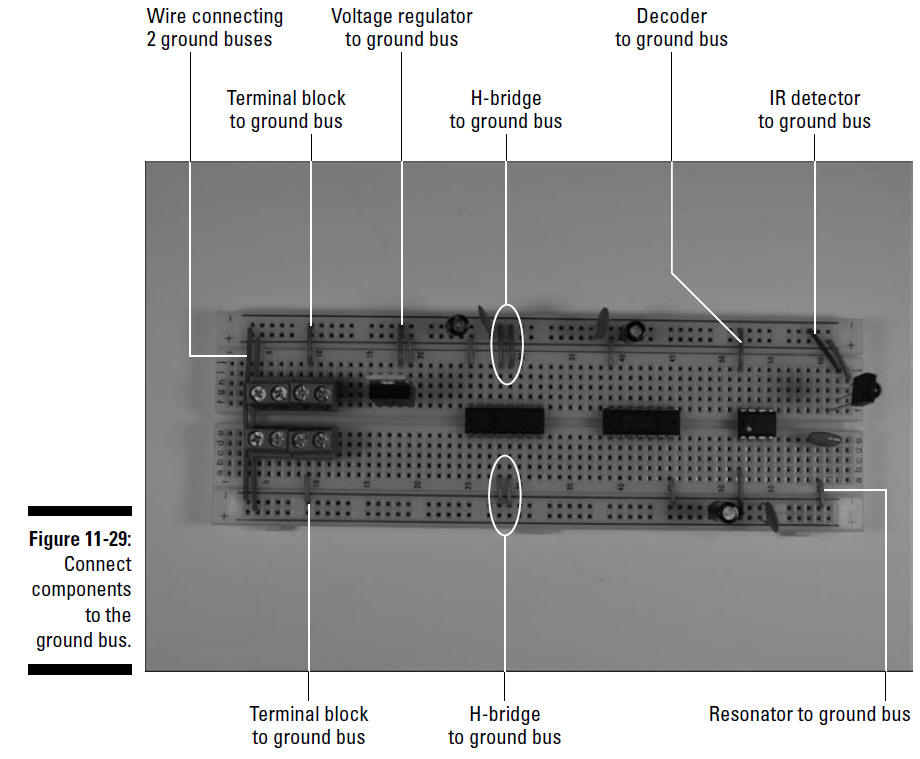
6. Insert wires to connect each component and
terminal to the ground bus (marked with a – on this breadboard)
and insert a wire to connect the two ground buses, as shown in
Figure 11-29.
The resonator in the center of the three leads is the ground
lead.
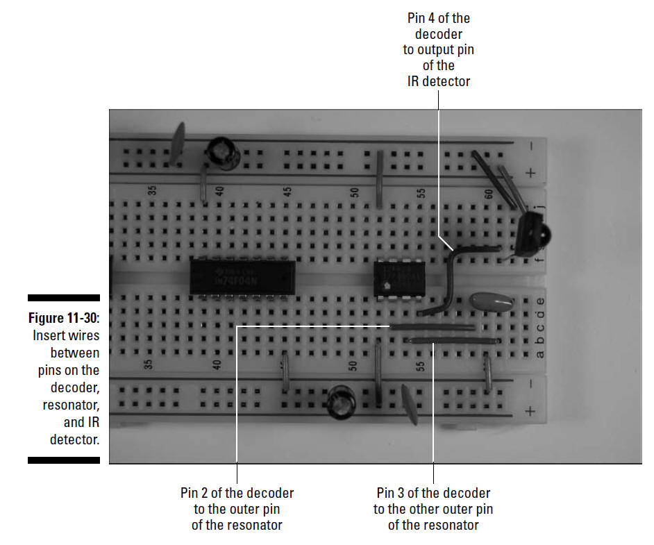
7. Insert wires to connect the decoder IC,
resonator, and IR detector, as shown in Figure 11-30.
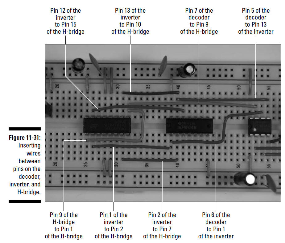
8. Insert wires to connect the decoder,
inverter, and H-bridge, as shown in Figure 11-31.
9. Insert wires to connect the terminal blocks
to the H-bridge and voltage regulator, as shown in Figure 11-32.