Scoping Out the Schematic
There are actually two breadboards to assemble
in this project: a transmitter circuit and a receiver circuit.
Take a look at the schematics for these two in the following
sections, along with helpful tips for reading them.
Transmitting at the speed of light
The
transmitter is what you use to operate the go-kart. The
transmitter circuit is shown in Figure 11-2.
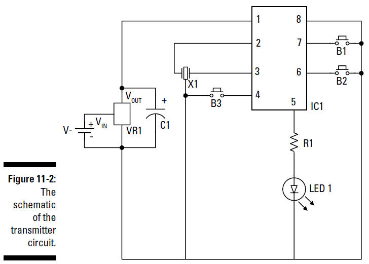
Here’s the gist of what’s going on:
VR1 is a
voltage regulator that takes the 6 volts supplied by the battery
pack and converts it to 5 volts, the maximum voltage
specified for the decoder (IC1).
The
capacitor (C1)
that’s placed
between the output pin and the ground pin of the voltage
regulator prevents any
oscillation
(wiggling around)
in the output voltage of the
regulator.
IC1
is an encoder whose job it
is to send out a signal that tells a decoder
on the receiver what to do. Pins 4, 6, and 7 are inputs
to the encoder (inputs 3, 2, and 1,
respectively). When a normally open (NO) pushbutton
switch
(B1, B2, B3)
tied to one of these pins is closed, the encoder modulates the
38 kHz carrier wave that tells the decoder IC in the receiver
exactly which button has been pressed. This signal goes
out through Pin 5 and then through
a 150 ohm resistor
(R1). The
resistor limits the current to about 22 milliamps; that’s so you
don’t burn out the LED. Thesignal then goes through the IR LED,
which generates an infrared signal.
X1
is a 4 MHz
ceramic resonator. This works with components within
the encoder to generate timing signals that help generate
the 38 kHz carrier wave and runs an
internal clock used to generate a signal that identifies
which pushbutton switch has been closed.
Receiving what the transmitter sends
Just like your TV receives the signal from a
remote control telling it to flip over to MTV, something has to
receive the transmitter signal to make the kart go. The receiver
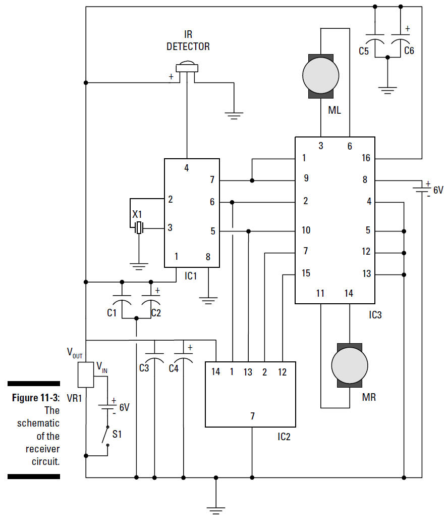
circuit is shown in Figure 11-3. Note what’s going on in this
schematic:
The
IR detector
contains a
photodiode; when the infrared signal reaches
the photodiode, it produces an electrical signal. This
electrical signal goes into Pin 4
of the decoder
(IC1).
IC1
then decodes the electrical signal sent by the transmitter.
Pressing and releasing a pushbutton
on the transmitter causes the decoder to
switch around the state of the corresponding output; Pin
7 is output 1, Pin 6 is output 2,
and Pin 5 is output 3. So, if the output pin is high, (5
volts), it will be changed to ground; if the output pin
is low (ground), it will be changed
to high (5 volts). The output stays at that voltage until
another signal appears to change it.
The
resonator (X1)
drives an
oscillator within the decoder to generate internal clock signals
used to decode the signal sent out by the encoder.
Like with the transmitter circuit, a voltage regulator
(VR1)
limits the supply voltage
to the ICs to 5 volts.
S1
is the power switch for
the receiver. You place a 10 microfarad capacitor
(C2, C4, C6)
and 0.1 microfarad
capacitor
(C1, C3, C5)
between the +V and ground
buses at the +V input of each of the ICs. These are used to
filter electrical noise from the DC
motors; that noise can prevent the ICs from operating correctly
because they won’t consistently
have the correct supply voltage. If you don’t add these
capacitors to the circuit, the motors could occasionally stop
running or stop responding when you press the transmitter
button.
Controlling motor behavior
To control the movement of the kart, you need to
be able to control the direction of both DC motors. Here’s what
will happen, depending on what the motors are doing:
Both motors are rotating forward:
The kart will move
forward.
Both motors are rotating backward:
The kart will move
backward.
If motor L is moving backward and motor R is moving forward:
The
kart will make a left turn.
If motor L is moving forward and motor R is moving backward:
The
kart will make a right turn.
In order to change the direction of the motors,
you need to change the direction of the current flowing through
the motor windings. A circuit called an
Hbridge
flips the direction
of the current through the motors. In the receiver
schematic (refer to Figure 11-3), IC3 contains two
H-bridges. (You can’t see the
H-bridges in the schematic, but trust us: They’re in there.
You’ll see where they go when you
get to the steps for assembling the go-kart.)
To control the motors, the H-bridge needs the
following inputs, as shown in Figure 11-3:
Pin 16: +V to
power the IC.
Pin 8: A
separate +V to power the DC motors.
This is why you need to use a second battery
pack; it helps isolate the ICs from electrical noise generated
by the DC motors that can cause the circuit to stop functioning
intermittently. Read about this in the upcoming parts list
section for this project.
Pins 1 and 9:
The signal, supplied from Pin 7 of the decoder (IC1), goes
to Pins 1 and 9 of the H-bridge in IC3. If Pin 7 (IC1) is
at +V, both DC motors turn on. If
Pin 7 of IC1 is at ground, both DC motors turn off.
Pins 2 and 7:
Pins 2 and 7 of the H-bridge determine in what direction
motor L rotates. To rotate motor L, the H-bridge requires
+V at Pin 2 and ground at Pin 7 in
order to go in one direction, or the opposite to go in
the other direction. In order to establish the +V and
ground connections for motor L, you connect Pin 6 of the decoder
to Pin 2 of the H-bridge and also
connect Pin 6 to IC3. IC2 inverts the signal so that +V becomes
ground or ground becomes +V. You then connect the
inverted signal to Pin 7 of the H-bridge; this gives you both
the +V and ground you need to
control the direction of motor L.
Pins 10 and 15:
These control the
direction of motor R in the same way
that Pins 2 and 7 control motor L. To rotate motor R, the
H-bridge requires +V at Pin 10 and
ground at Pin 15, or the opposite to go the other way.
Connect Pin 5 of IC1 to Pin 10 of the H-bridge and also
connect Pin 5 of IC1 to IC2. IC2 then inverts the signal so that
+V becomes ground or ground becomes
+V. That signal now goes to Pin 15 of the H-bridge.