Building the go-kart
If you’ve followed this chapter to this point,
all the little wires and doohickeys in the transmitter and
receiver circuit are in place to make your go-kart go. However,
one thing is missing: the kart itself. This consists of a
platform on which you affix
The
receiver
The
motors
A
switch to turn the power on and off
Something to cover the chassis
Although the covering is optional, it makes the
kart look cooler. More importantly, a covering prevents your
kids or pets from poking a finger or paw where they shouldn’t
and pulling wires loose.
To build the kart itself, follow these steps:
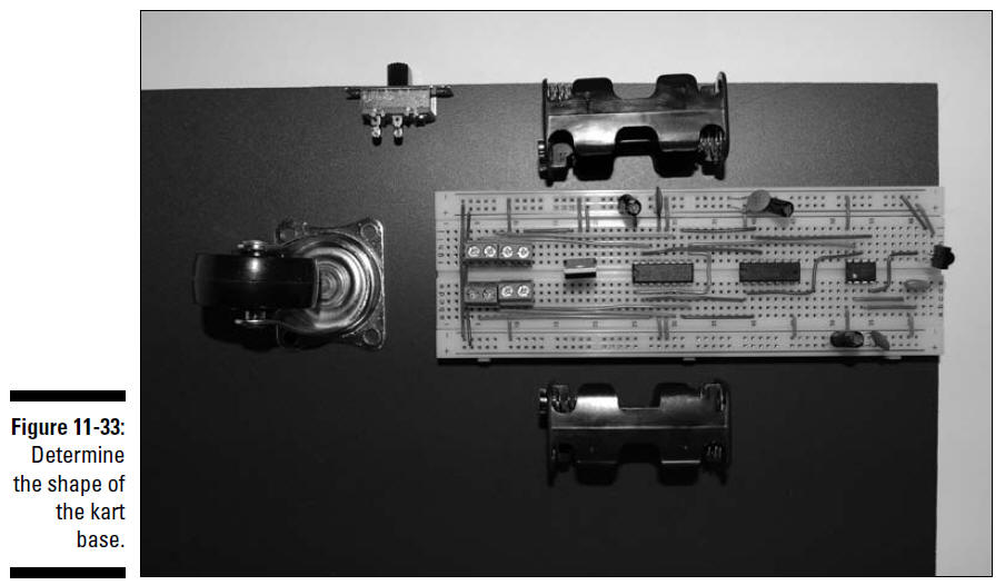
1. Place the breadboard, battery packs, caster,
and power switch on the
1
⁄2"
PVC or plywood sheet, as shown in Figure 11-33.
This will help you to determine how large to
make the base of the kart.
We chose a
1⁄2"
PVC sheet, 61⁄2"
wide and 9" long, which can hold all the
components and still leave enough room to rest the top of
the kart on the base. You can use a
pencil to mark where to cut the
1⁄2"
PVC sheet.
2. Mark a location between the breadboard and
the bumper switch where you will drill a hole to feed the wires
to the motors.
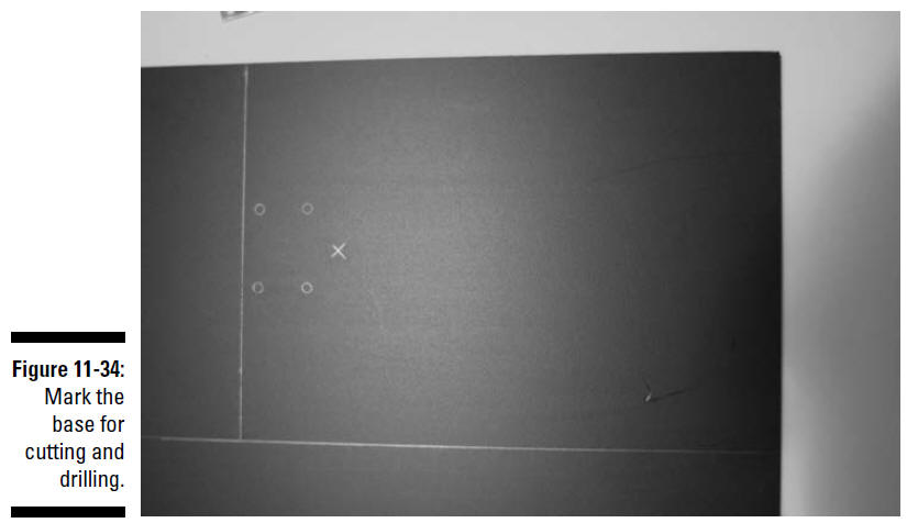
3. Use the base of the castor as a template to
mark the four holes you will drill to mount it to the body.
Figure 11-34 shows the marked PVC sheet.
4. Cut the sheet along the lines you drew (a
hacksaw or any fine-toothed saw should do the job), and then use
a
1⁄4"
bit to drill a hole where you
marked the feed-through hole in Step 2.
5. Use a
1⁄8"
bit to drill the holes used to attach the castor.
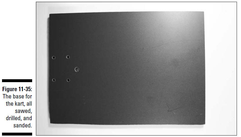
Use sandpaper or a file to smooth any rough
edges. Figure 11-35 shows the base after it’s been cut and
drilled.
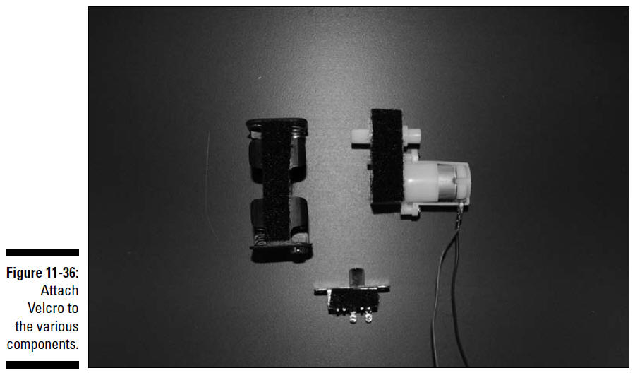
6. Attach Velcro to the battery packs, motors,
and switch, as shown in Figure 11-36.
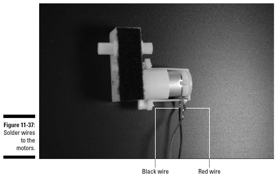
7. Solder 12" wires to the motors, as shown in
Figure 11-37.
By using different wire colors (we used red and
black), it’s easier to identify which goes to each pin in the
terminal blocks on the breadboard so you can control which
direction the motors turn.
8. Stick some Velcro to the base of the kart
where the motors will be attached and then attach the motors;
see Figure 11-38.
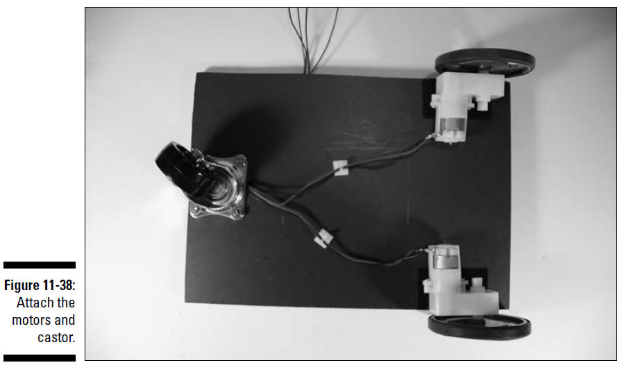
9. Attach the castor, using
5⁄8"
6-32 screws and nuts, also shown in
Figure 11-38.
10. Feed the wires through the
1⁄4"
hole and secure the wires with the wire
clips (as shown in Figure 11-38); then slip the wheels on
the motor shafts and secure the
wheels with the screw provided.
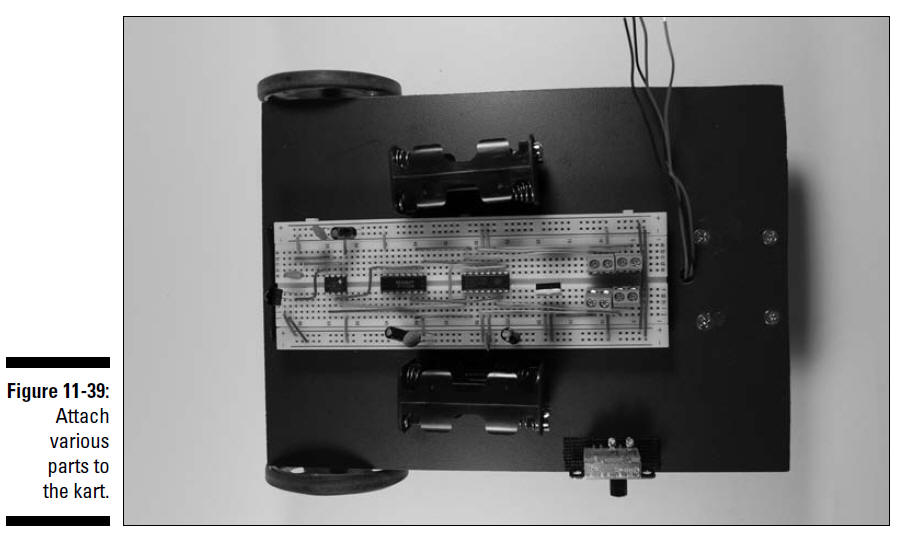
11. Stick Velcro to the base of the kart and
attach the battery packs, switches, and breadboard to the top of
the base, as shown in Figure 11-39.
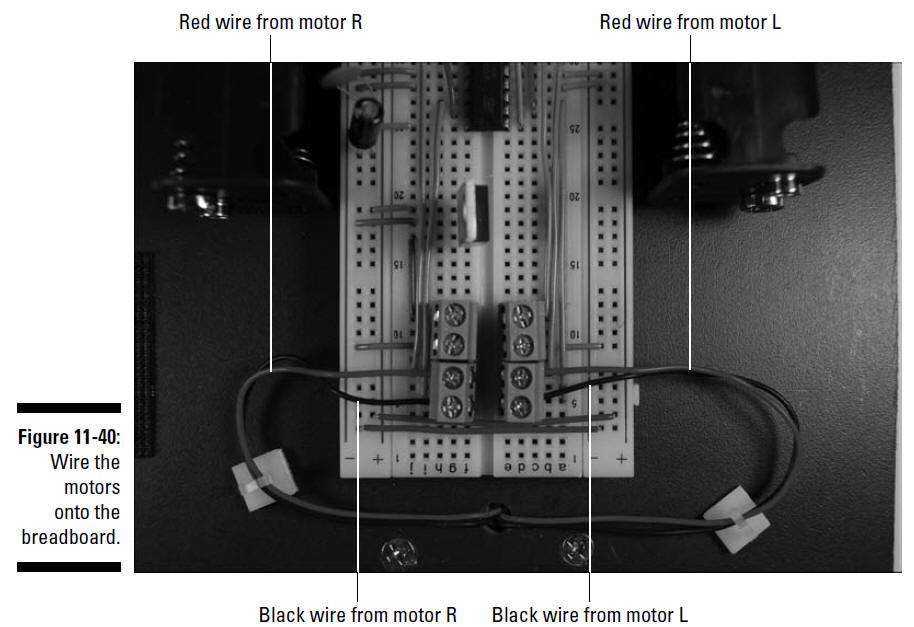
12. Attach wires from the motors to the terminal
blocks, as shown in Figure 11-40.
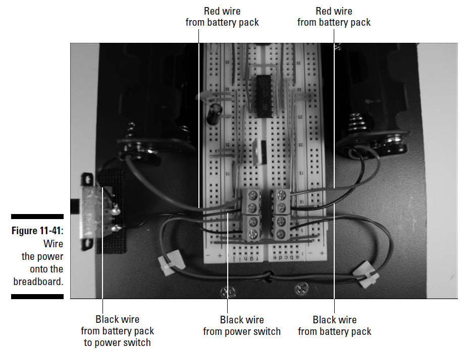
13. Attach wires from the battery packs to the
terminal blocks and power switch, as shown in Figure 11-41, and
solder the wires attached to the power switch lugs.
14. With a mini hacksaw, cut openings in the
back of the plastic kart top.
One opening will allow the IR detector to peek
out and detect a signal; the other opening is for the power
switch in the side. Make sure you’re using a top made of
flexible plastic so it cuts easily. Wear safety glasses in case
a piece flies off while you’re cutting.
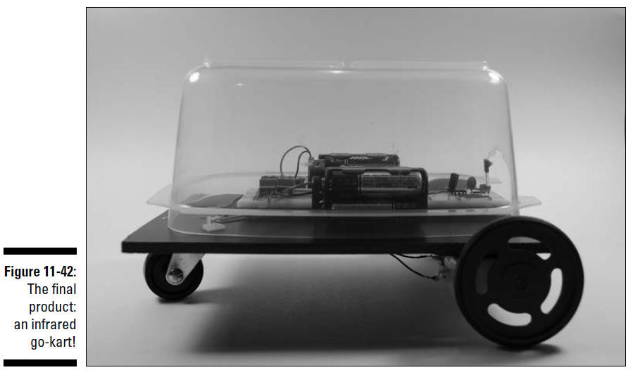
15. Rest the bubble on the kart, as shown in Figure 11-42.