

Focusing Sound With a Parabolic Microphone
Scoping Out the Schematic
By now, your mind is likely a-flutter with ideas for sounds floating around your neighborhood that you’re dying to pick up, so it’s time to get going on the schematic for the board, which you can see in Figure 6-2.
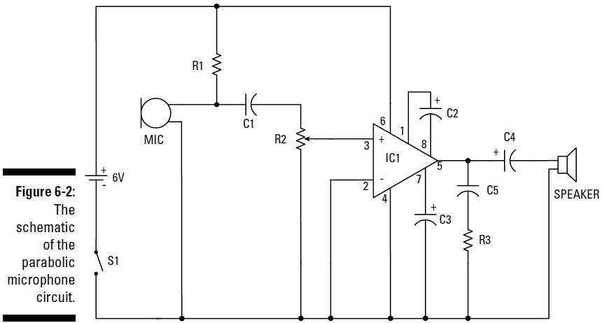
The following is a list of the schematic elements for your parabolic microphone:
The circuit starts with the electret microphone, which transforms sound waves into electrical signals. R1 connects the microphone to positive voltage and supplies the 3 volts required to make the microphone function. C1 is a capacitor that blocks the DC voltage on the input signal and allows the AC signal to pass. IC1, an LM386N-1 audio amplifier, takes the electrical signal generated by the electret microphone and amplifies it to provide sufficient power to generate sound through the headphones. R2 is a potentiometer you use to control the sound volume. C2 sets the voltage gain of IC1 to 200. Therefore the voltage out is 200 times the voltage in. C3 improves the stability of the LM386 amplifier to prevent problems, such as oscillation. Oscillation can turn that nice little birdcall into a hodgepodge of unintelligible sounds. C4 removes any DC offset from the output of the LM386 amplifier. C5 acts as a current bank for the output. This capacitor drains when sudden surges of current occur and refills with electrons when the demand for current is low.