
Focusing Sound With a Parabolic Microphone
Mounting switches and more on the box
It’s time to drill all kinds of holes and pop various components into the box. Follow these steps to do so:
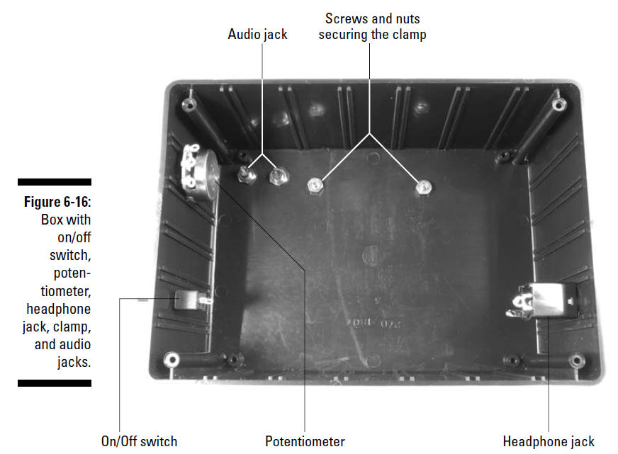
1. Drill holes in the box where you will mount the potentiometer, audio jacks, headphone jack, clamp, and on/off switch, as shown in Figure 6-16.
We put the on/off switch and potentiometer on one side of the box, the headphone jack on the opposite side of the box, and the phono jacks on the bottom of the box. We kept the headphone jack to one side to keep the output signal from feeding into the input of the circuit (for example, by being near the microphone wires), which could cause feedback.
See "Discovering Schematics" for more information about choosing drill bit sizes for particular components and other advice on how to customize a box for your projects. Make sure you use safety glasses when drilling and clamp the box to your worktable!
2. Slip the shaft of the on/off switch through the drilled hole and secure with the nut provided.
3. Slip the shaft of the potentiometer through the drilled hole and secure with the nut provided.
4. Slip the knob on the potentiometer shaft and secure with the set screw.
5. Slip the threads of the headphone jack through the drilled hole and secure with the nut provided.
6. Slip the threads of the audio jacks through the drilled holes and secure with the (you guessed it) nuts provided.
7. Slip 8-32 screws through holes in the clamp and the holes you drilled in the box and secure with nuts from the inside of the box.
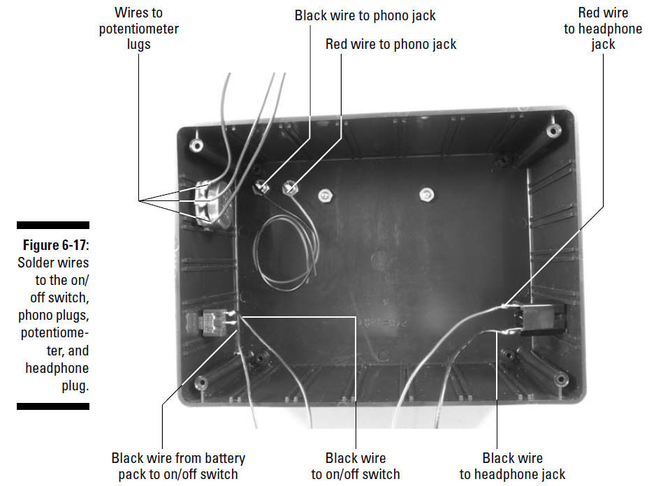
8. Solder the black wire from the battery pack to one lug of the on/off switch and solder an 8" black wire to the remaining lug of the on/off switch, as shown in Figure 6-17.
9. Solder one 8" black wire to the lug on one of the audio jacks and solder one 8" red wire to the lug on the other audio jack, as shown Figure 6-17.
10. Solder 8" wires to each of the three potentiometer lugs, as shown in Figure 6-17.
11. Solder one 8" black wire and one 8" red wire to the lugs of the headphone jack, as shown Figure 6-17.
The red wire should go to the contact that touches the tip of the headphone plug.Okay, we’ll say it again: Heed all the safety precautions about soldering that we give you in "Avoiding Shocks" Don’t ever leave your soldering iron on and unattended. And to avoid damage from flying pieces of solder, wear your safety glasses!