
Focusing Sound With a Parabolic Microphone
Building an amplifier circuit
The first step in building a parabolic microphone is to tackle the circuit that forms its electronic brains. Here are the steps involved:
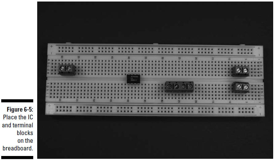
1. Place LM386N-1 (IC2) and five terminal blocks (TB) on the breadboard, as shown in Figure 6-5.
The five terminal blocks shown in this figure will be used to connect two wires each to various components in the circuit. The wires from these five terminal blocks will go to the battery pack, the on/off switch, the microphone, the speaker, and the potentiometer.
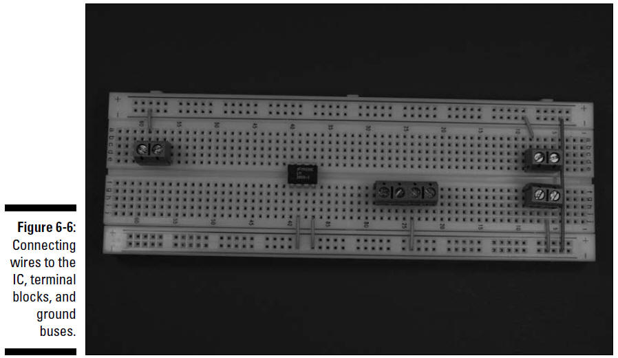
2. Insert wires to connect the IC and the terminal blocks to the ground bus and insert a wire between the two ground buses to connect them, as shown in Figure 6-6.
Six shorter wires connect components to ground bus; the long wire on the right connects the two ground buses.
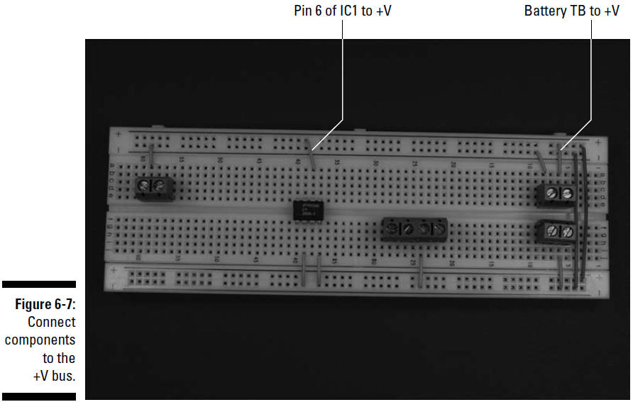
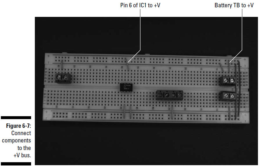
3. Insert wires to connect the IC and the terminal blocks to +V, and a wire between the two +V buses to connect them, as shown in Figure 6-7.
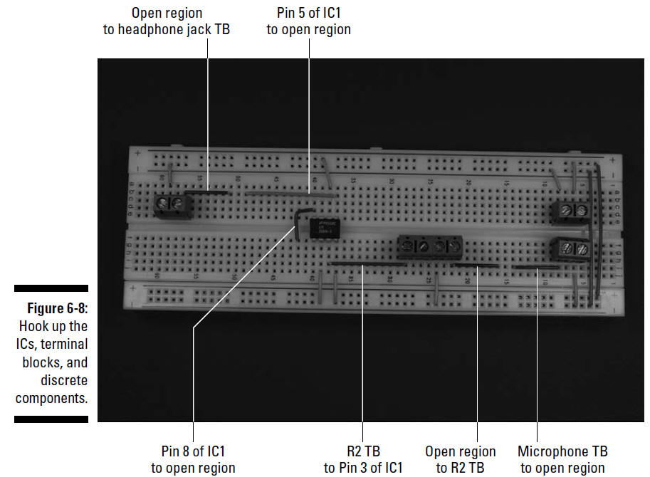
4. Insert wires to connect the ICs, terminal block for the microphone cartridge, terminal blocks for the potentiometer (R2), terminal block for the headphone jack, and discrete components, as shown in Figure 6-8.
4. Insert wires to connect the ICs, terminal block for the microphone cartridge, terminal blocks for the potentiometer (R2), terminal block for the headphone jack, and discrete components, as shown in Figure 6-8.
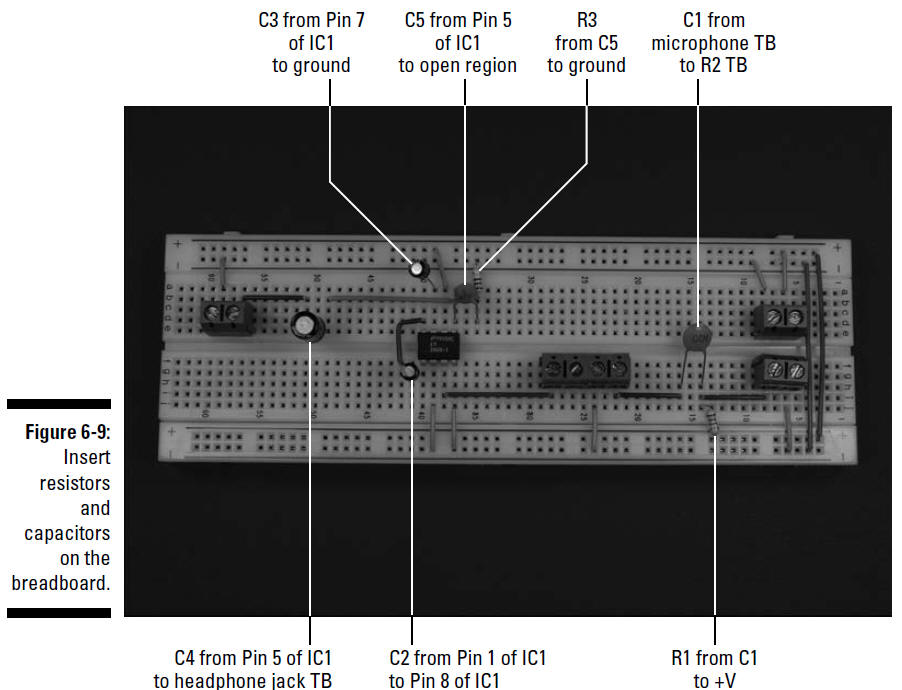
5. Insert the 0.047 microfarad capacitor (C5), two 10 microfarad capacitors (C2 and C3), one 100 microfarad capacitor (C4), one 0.1 microfarad capacitor (C1), one 5.6 kohm resistor (R1), and one 10 ohm resistor (R3) on the breadboard, as shown in Figure 6-9.
When inserting electrolytic capacitors, be sure to check the schematic for where to insert the longer + lead. We discuss in "Discovering Schematic" how you can determine how short to clip the leads of many of these components to make them fit neatly on the breadboard. And you knew we were going to say it: Make sure you wear your safety glasses when clipping leads!