

Making Light Dance to the Music
Adding the rest of the doohickeys
After the circuit and LEDs are pretty much taken care of, you have a lot of other things still sitting on your workbench, like the microphone, potentiometers, a switch, and one or two more things. You have to take care of assembling these before your project will work. Follow these steps to take care of all the rest of the parts that make the music dance:
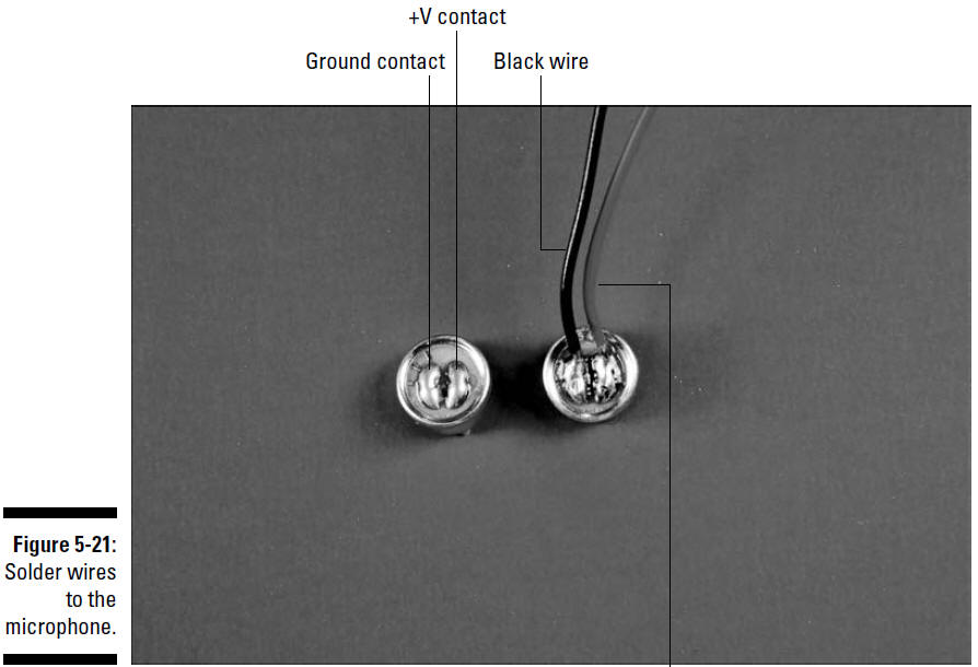
1. Solder a 12" black wire to the microphone ground contact and a 12" red wire to the microphone +V contact.
Figure 5-21 identifies the microphone contacts.
2. Drill holes in the box where you will insert the microphone and on/off switch.
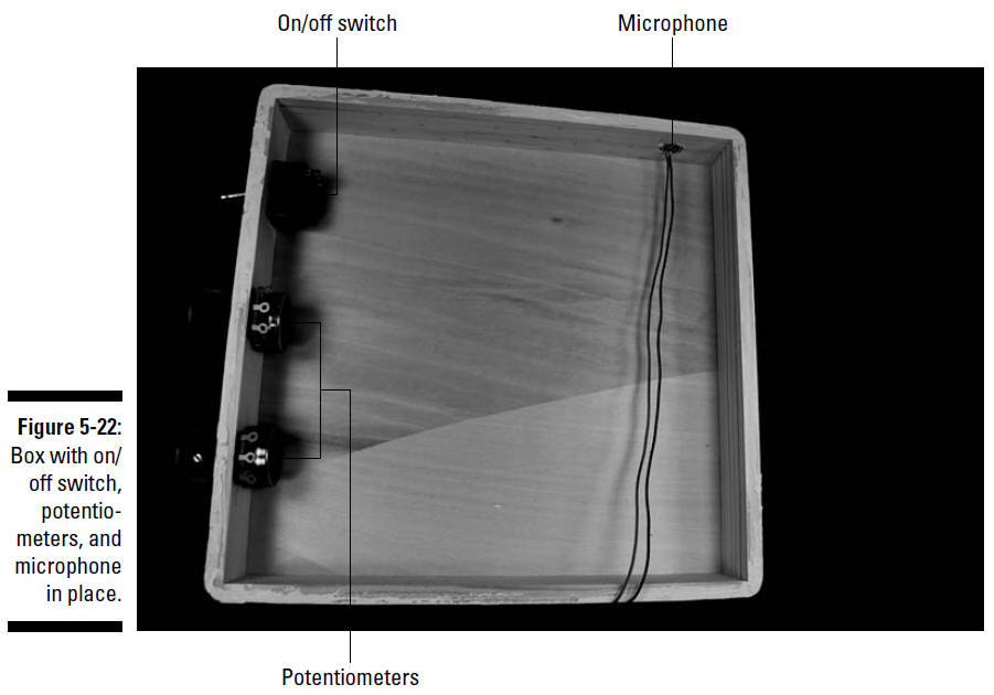
We put both the potentiometers and on/off switch on one side of the box and the microphone on another side, but the placement is really up to you. Chose a drill bit size for the microphone hole so that the microphone has a slip fit. The upcoming Figure 5-22 shows where we place these components. See Chapter 4 for more information about choosing drill bit sizes for particular components and other pieces of wisdom on how to customize a box for your projects. Make sure you use safety glasses when drilling, and clamp the box to your worktable!3. Slip the shaft of the on/off switch through the drilled hole and secure with the nut provided.
4. Slip the shaft of the potentiometers through the drilled holes and secure with the nuts provided.
5. Slip a knob over the shaft of each potentiometer and tighten the knob with the set screw provided.
The tread on potentiometers is about 1⁄4" long, so if the wall of your wooden box is 1⁄4" thick, you won’t be able to use the nut to secure the potentiometer. Instead, check to make sure that the potentiometer shaft extends far enough beyond the box to allow the knob set screw to tighten on the shaft. If the shaft extends far enough, glue the face of the potentiometer to the box, making sure that you don’t get any glue on the rotating shaft of the potentiometer. If the shaft doesn’t protrude quite enough, use a small chisel to remove some wood on the inside of the box to let the potentiometer shaft extend a little farther before you glue.6. Slip the microphone into its drilled hole with a press fit.
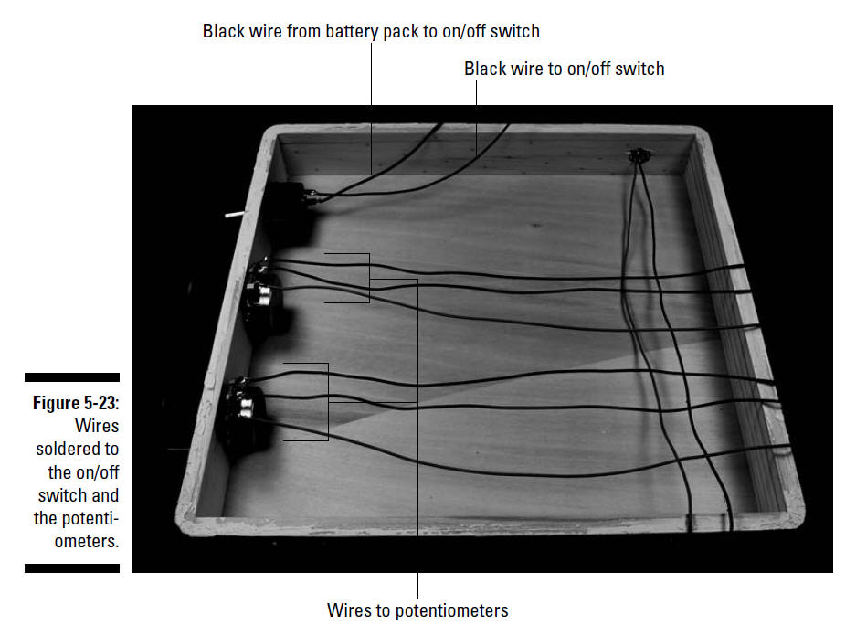
Figure 5-22 shows the on/off switch, potentiometers, and microphone in place in the box.7. Solder 12" black wires to each of the three potentiometer lugs, as shown Figure 5-23.
8. Solder the black wire from the battery pack to one lug of the on/off switch and solder a 12" black wire to the remaining lug of the on/off switch.
Figure 5-23 shows the switch after the wires are soldered.9. Attach Velcro to the breadboard and the box and then secure the breadboard in the box.
10. Attach Velcro to the battery pack and the box and then secure the battery pack in the box.
11. Insert the wires from the LEDs, battery pack, and the on/off switch to the terminal blocks on the breadboard, as shown in Figure 5-24.
Use the following as a key to the numbered callouts in Figure 5-24.1. Red wire from LED +V bus
2–5. Wires from pair of red LEDs
6–9. Wires from pair of green LEDs
10. Red wire from battery pack
11. Black wire from on/off switch
12. Red wire from microphone
13. Black wire from microphone
14 and 17. Wires from right potentiometer lug
15 and 18. Wires from center potentiometer lug
16 and 19. Wires from left potentiometer lug
12. As you insert the wires, cut each of them to the length needed to reach the assigned terminal block and strip the insulation from the end of the wire.
13. Secure the wires with wire clips.