Making the circuit
Time to go one-on-one with your breadboard. Here
are the steps involved:
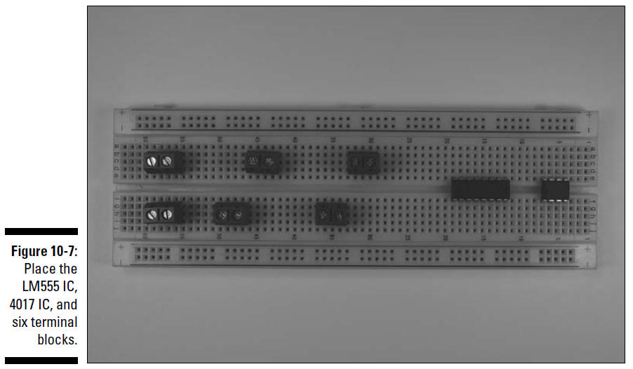
1. Place the LM555 IC, the LM4017 IC, and six
terminal blocks on the breadboard, as shown in Figure 10-7.
The six terminal blocks in this figure will be
used to connect two wires each to various components in the
circuit. The wires from one terminal block go to the battery
pack, and the wires from each of the other terminal blocks go to
one of the LED/resistor arrays.
2. Insert discrete components on the breadboard, as shown in
Figure 10-8.
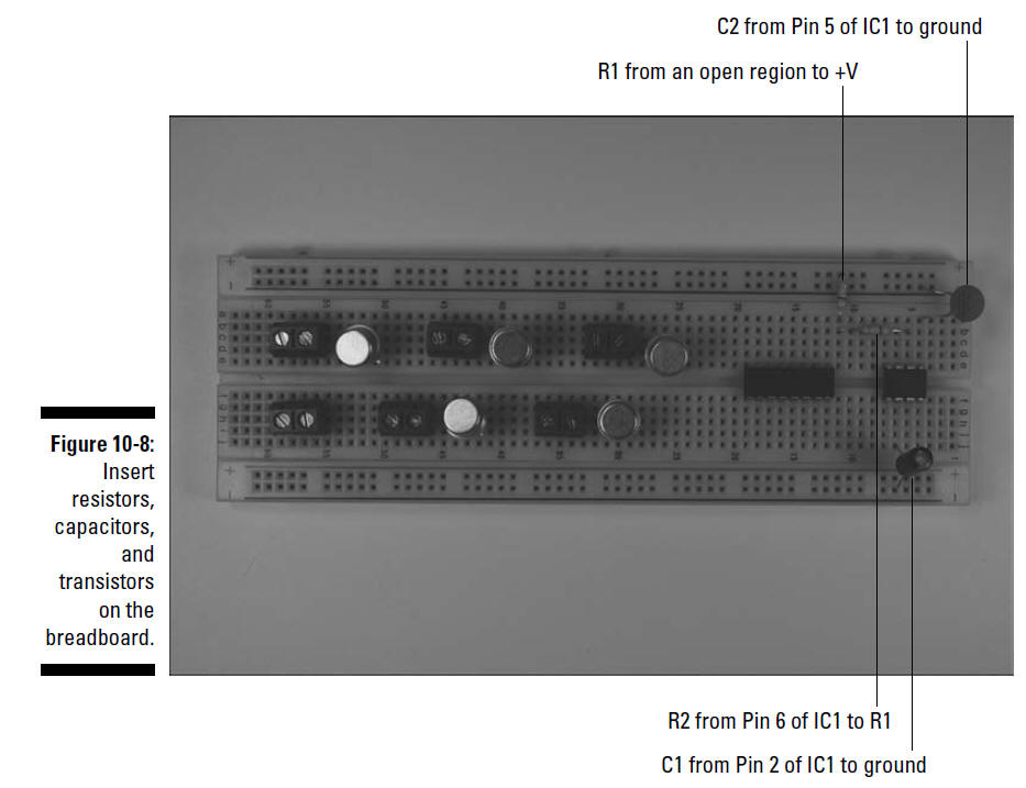
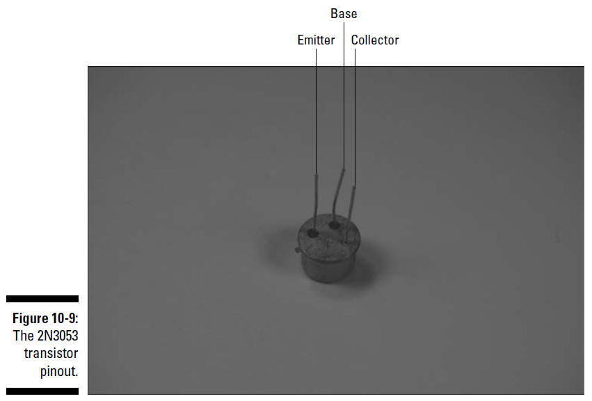
Figure 10-9 identifies the pins of the 2N3053
transistors. You insert each transistor pin into a separate
breadboard row, placing the collector pin nearest to the
terminal block, and then insert C1 with the shorter of the two
pins of C1 in the ground bus and the longer pin in the same
breadboard row as Pin 5 of IC1.
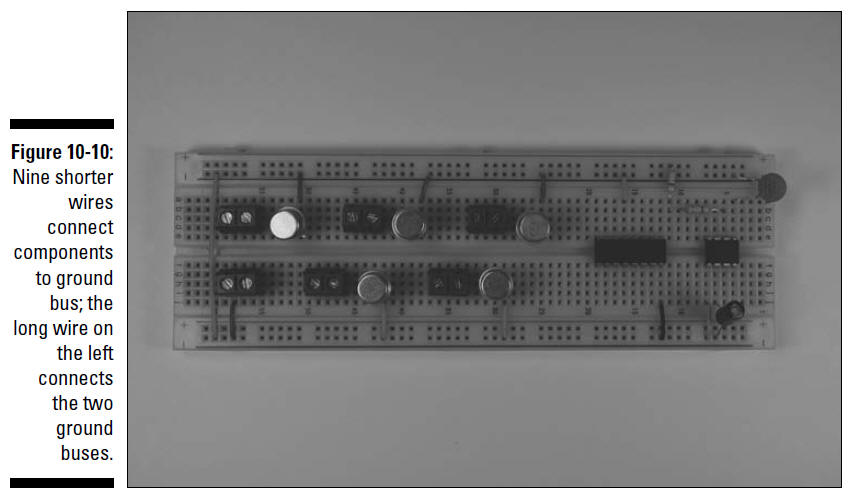
3. Insert wires to connect the ICs, the battery
pack terminal block, and the emitter pin of the transistors to
the ground bus. Then insert a wire between the two ground buses
to connect them, as shown in Figure 10-10.
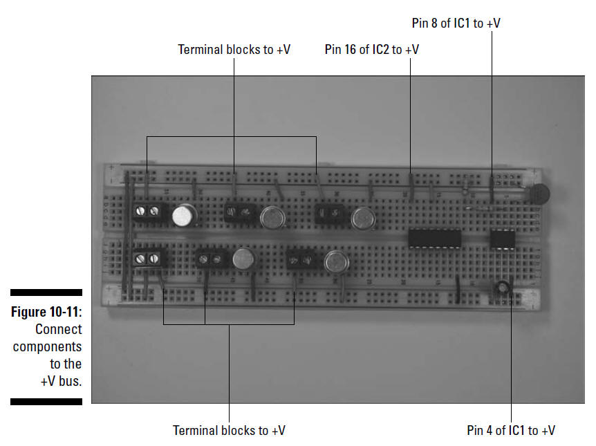
4. Insert wires to connect the ICs and the
terminal blocks to the +V bus, as shown in Figure 10-11.
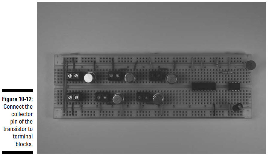
5. Insert wires to connect the collector pin of
the transistors to the terminal blocks, as shown in Figure
10-12.
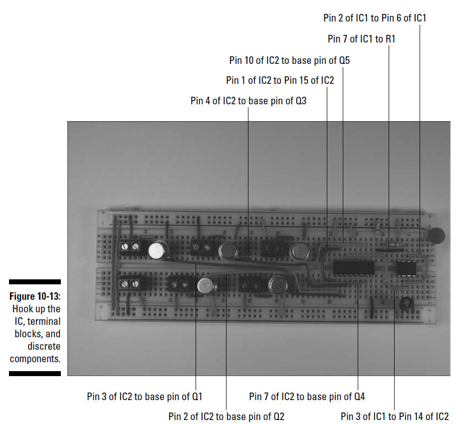
6. Insert wires to connect the ICs, terminal
blocks, and discrete components, as shown in Figure 10-13.