Making dolphins
All the brains of the circuit assembled in the
previous section are there to make the dolphin light display
work.
Follow these steps to create your dancing
dolphin display:
1. Make five dolphin (or another figure)
stencils, each about 11" high.
You can create a template by printing a piece of
clip art or other simple drawing and enlarging it with a copier.
2. Decide where you want to place the dolphins
on the plywood and use double-sided tape to affix the templates.
3. Use a marking pen to mark where you want to
place the LEDs on the plywood to show the outline of the
dolphins.
We used 38 LEDs per dolphin. We spaced the marks
about 11⁄2"
apart in the parts of the dolphin where there was little change
in shape. Where the dolphin’s shape was a bit more complex (for
example, the nose and tail), we spaced them more closely.
4. Drill test holes in a piece of scrap wood to
determine the size of drill bit that you should use to give a
press fit for the LEDs.
We used a
13⁄64" drill
bit.
5. Drill holes for the LEDs at the locations
that you marked in Step 3.
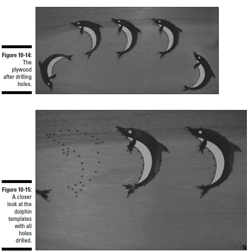
The plywood after drilling is shown in Figures 10-14 and
10-15.
6. Pick a dolphin and start inserting LEDs in
the drilled holes.
We suggest starting at either end of the plywood
sheet so the LED leads of a finished dolphin aren’t in your way
while you work.
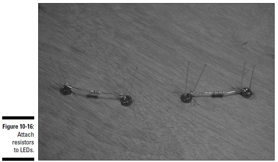
7. Attach resistors between every other LED, as
shown in Figure 10-16.
Attach the resistors to the short lead on the
first LED of each pair and to the long lead on the second LED of
each pair. At this point, leave the long lead on the first LED
and the short lead on second LED alone.
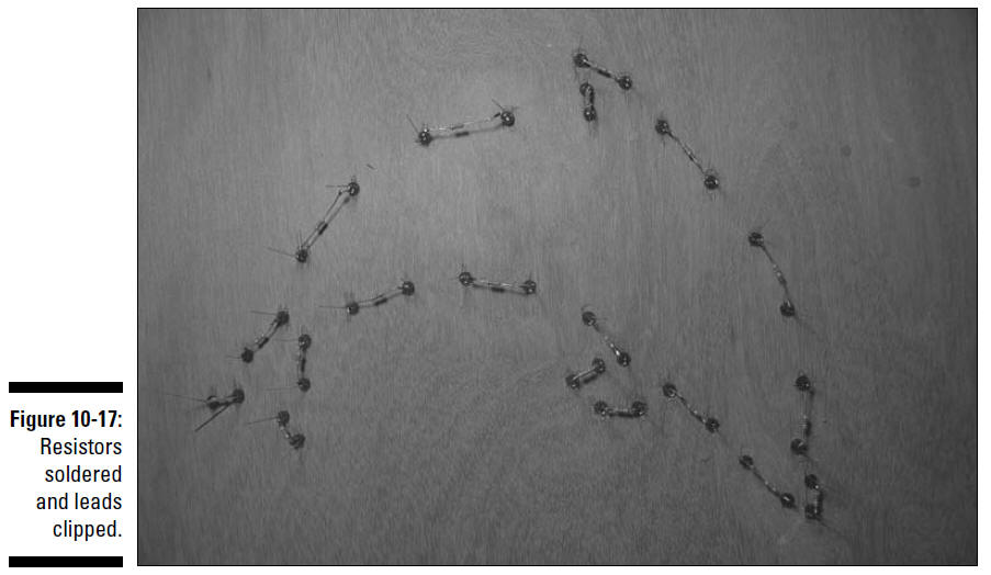
8. Solder the resistors to the leads and clip
the leads just above the solder joint.
Clip only the leads to which you have soldered
resistors. Figure 10-17 shows how the dolphin board should look
at this point.
Be sure to heed all the safety precautions about
soldering that we provide in Chapter 2. For example, don’t leave
your soldering iron on if you have to step away. And just in
case a bit of solder has an air pocket that could cause it to
pop, wear your safety glasses whenever you solder.
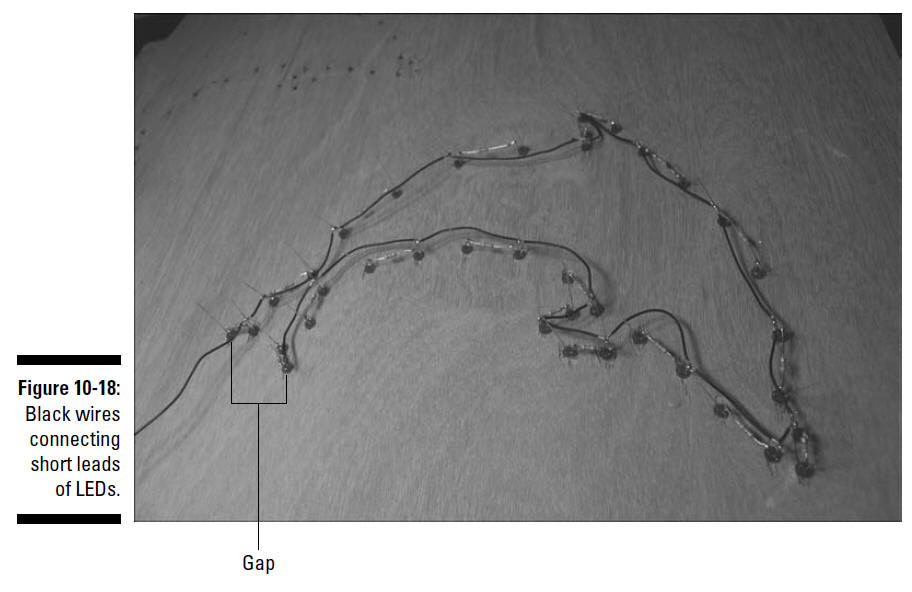
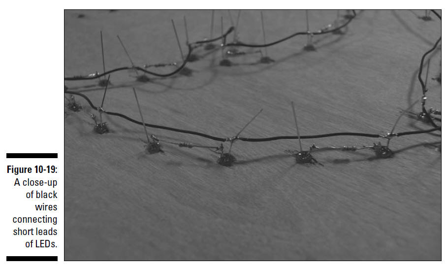
9. Connect the short leads on every other LED to
short lengths of 20 gauge black wire, as shown in Figures 10-18
and 10-19.
Figure 10-18 shows a gap without a black wire
across the tail of the dolphin. One of the LEDs at the tail with
a short lead has only one black wire attached, and the other has
a 2' 20 gauge black wire attached; you connect this wire to a
terminal block on the breadboard in Step 20.
10. Solder the black wires to the leads, as shown in Figure
10-19.
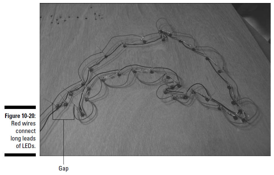
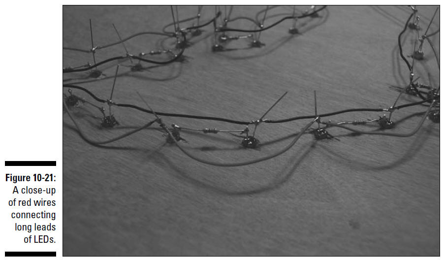
11. Connect the long leads on every other LED to
short lengths of 20 gauge red wire, as shown in Figures 10-20
and 10-21.
Figure 10-20 shows a gap where no red wire is
strung across the tail of the dolphin. One of the LEDs at the
tail with a long lead has only one red wire attached; the other
has a 2' 20 gauge red wire attached, which you connect to a
terminal block on the breadboard in upcoming Step 20.
12. Solder the red wires to the leads, as shown
in Figure 10-21.
13. Clip the LED leads just above the solder
joint.
14. Make sure that the LED leads and solder
joints don’t touch each other and then coat them with liquid
electrical tape to help prevent any shorts if wires are bent or
pushed together.
15. Repeat Steps 6–11 for each dolphin until you
install and wire the LEDs for all five.
16. Chose a location on the plywood sheet to
place the battery pack so that you can reach the on/off switch.
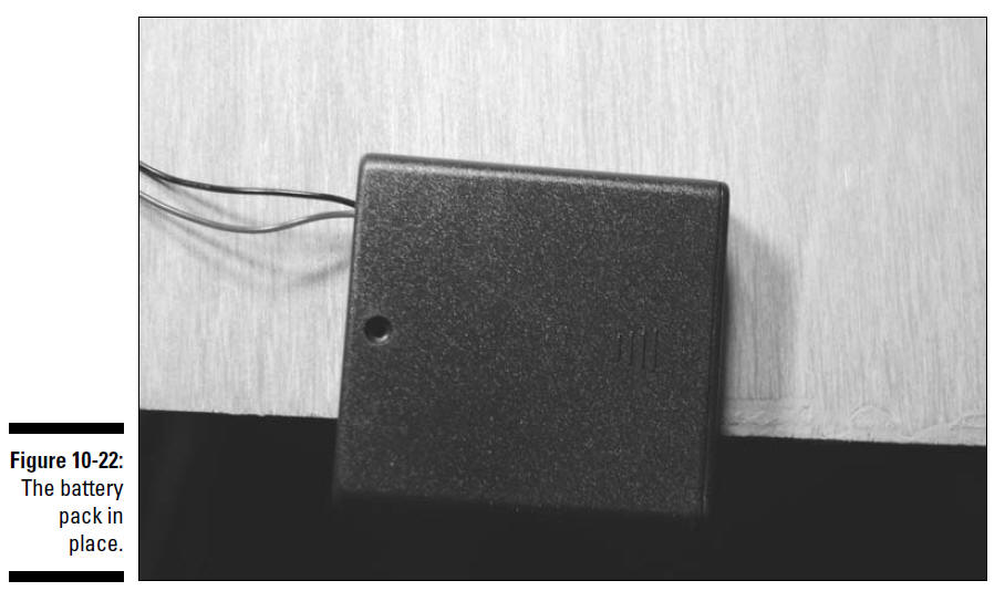
17. Attach Velcro to the battery pack and the
plywood so that you can attach the battery pack to the plywood,
as shown in Figure 10-22.
18. Chose a location on the plywood sheet where
you will place the breadboard.
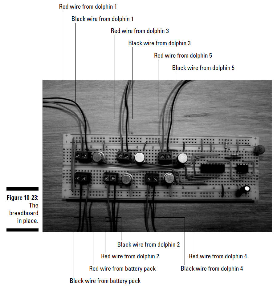
19. Attach Velcro to the breadboard and the
plywood and then attach the breadboard to the plywood, as shown
in Figure 10-23.
20. Insert the wires from the battery pack and
the dolphins to the terminal blocks on the breadboard, as shown
in Figure 10-23.
If the wire on the battery pack isn’t long
enough to reach the breadboard, splice and solder longer 20
gauge red and black wires. Protect the splices with electrical
tape or heat shrink tubing.
21. Secure the wires with wire clips.
22. Add the protective backing by performing the
following steps:
a. Drill holes for 6-32 screws in six locations
on each plywood sheet to attach the standoffs between the two
plywood sheets.
b. Secure the six standoffs to the plywood sheet
on which you’ve placed the LEDs, using 6-32 screws.
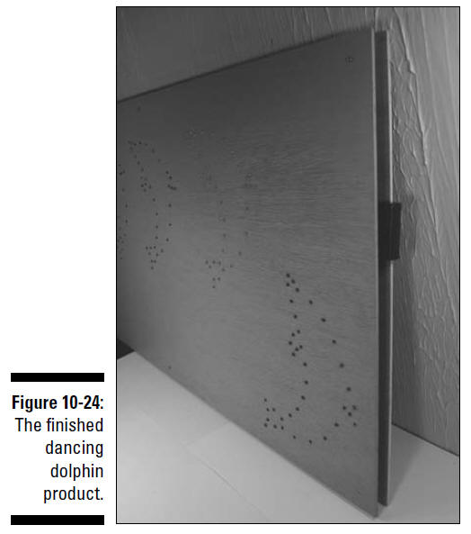
c. To finish off the project, secure the second
plywood sheet to the six standoffs using 6-32 screws, as shown
Figure 10-24.