Scoping Out the Schematic
You have but one breadboard to put together for
this project, but we make up for that by making you string 5
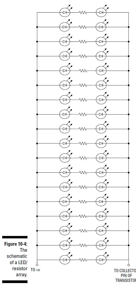
LED/resistor arrays, each containing 38 LEDs and 19 resistors.
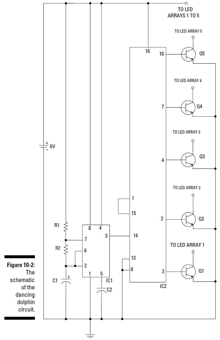
Take a look at the schematic for the board, as
shown in Figure 10-2.
Getting in the swim: Exploring
the dolphin circuit
To make your dolphin shapes light up in
sequence, you need to make a circuit that uses a timer chip and
a decade counter chip in combination with some resistors and a
capacitor plus some transistors. Together, these control how
often each of the five dolphins lights up and how long each
stays lit.
A
decade counter essentially takes a square wave and
breaks it up into ten pulses. For those of you who took Latin,
you’ll recognize
decade as related to the magic number ten. Read more
about this counter in the following list.
Here’s the overview of the schematic elements
that you use to control your terpsichorean dolphins:
IC1 is a key
component of this circuit; it’s an LM555 timer chip that you
use to generate a square wave at its output on Pin 3.
IC2 is the
other key component of this circuit. This is a 4017 decade
counter that takes a square wave and generates ten
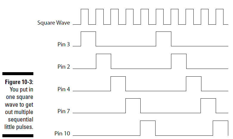
sequential pulse outputs. A 4017
decade counter does this by placing +V on one of its output pins
at a time, one after the other. The 4017 decade counter switches
to the next output pin at the start of each cycle of the square
wave generated by the timer, as shown in Figure 10-3.
This allows you to control the rate
at which the 4017 decade counter switches +V to each output pin;
this is done by controlling the frequency of the square wave
generated by the LM555 timer chip. Because we didn’t want
ten dolphins, we connected the
sixth output pin (Pin 1) to the reset pin (Pin 15). This applies
+V to the reset pin after five dolphins dance across the wall
and also resets the counter to the
first output pin, skipping the last four
output pins altogether.
R1, R2, and C1
are, respectively, two resistors and a capacitor that form the
RC circuit that determines the frequency of the square wave
generated by the LM555 timer chip.
Q1, Q2, Q3, Q4, and Q5
are 2N3053 transistors
that turn on when the output pin of
the 4017 decade counter they’re connected to is switched
to +V. You use these transistors to supply the necessary
current — about 190 milliamps — to
light the 38 LEDs in each group.
The 555 timer IC generates a square wave from
its output. The frequency of the square wave that is generated
is determined by how fast the capacitor fills and drains. You
calculate how fast the capacitor fills to two-thirds of its
capacity or drains to one-third of its capacity by using the
RC time
constant equation.
You can read more about
this equation in Chapter 9.
C2
is a capacitor that
reduces the occurrence of noise on Pin 5 of the
LM555, which could cause false triggering of the IC. This
noise can occur if Pin 5 is left
unconnected (also called
floating).
Setting up the light show
The circuit won’t mean a thing if you don’t set
up the lights for it to control. That’s where the elements of
the LED/resistor arrays come in. An array, in this case, equals
the lights that define one whole dolphin. These five arrays each
include
38 LEDs,
which light up when a
river of current runs through them
19
resistors,
which are resistors that limit the current running through the
LEDs in series with each resistor to approximately 10 milliamps
Take a look at the schematic for these in Figure 10-4.
Notice that we have not assigned a
number to each LED and resistor. That is because we have 190
LEDs and 95 resistors among the 5 dolphins — and
we don’t have time.
These LEDs and resistors are wired together such
that two LEDs and one resistor are in series. When +V is
applied, current runs through each component sequentially. Each
group of two LEDs and one resistor are connected parallel with
the other groups of LEDs and resistor. Because 19 LED/resistor
groups are in each array, the total current running through an
array is approximately 190 milliamps.