Taking Things Step by Step
Creating your Couch Pet-ato involves wiring the
circuit; installing the speaker, microphone, battery, switches,
and circuit board in the box; and then connecting the whole
shebang.
Start at the beginning — by wiring the circuit.
Follow these steps to build your Couch Pet-ato circuit (but be
sure not to let Rover know what you’re up to).
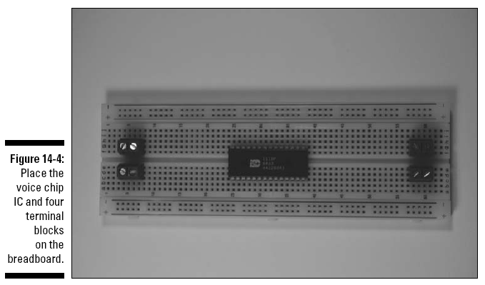
1. Place the voice chip IC and four terminal
blocks on the breadboard, as shown in Figure 14-4.
The four terminal blocks shown in this figure
will be used to connect two wires each to various components in
the circuit. The wires from these four terminal blocks go to the
battery pack, on/off switch, record switch, and microphone,
respectively.
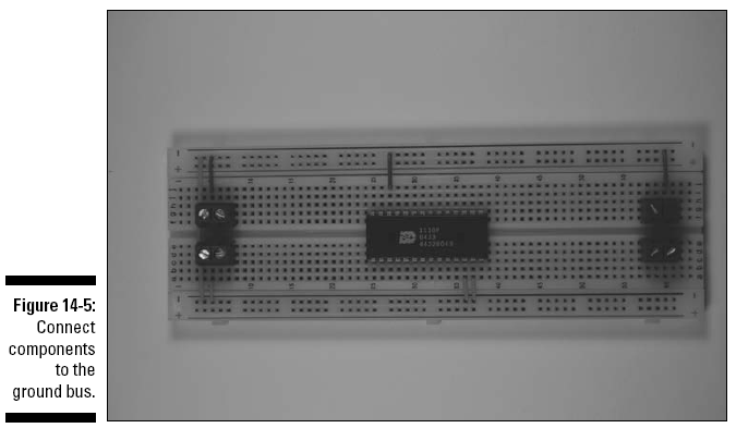
2. Insert wires to connect each component and
terminal to the ground bus and insert a wire between the two
ground buses to connect them, as shown in Figure 14-5.
In this figure, six shorter wires connect
components to the ground bus (marked with a – on this
breadboard); the long wire on the left connects the two ground
buses.
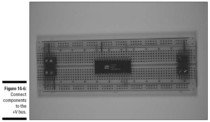
3. Insert wires to connect each component and
terminal to the +V bus and insert a wire between the two +V
buses to connect them, as shown in Figure 14-6.
In this figure, four wires have been added:
• Three shorter wires connect components to +V
bus (marked with a + on this breadboard).
• The long wire on the left connects the two +V
buses.
4. Insert wires to connect the voice chip IC to
the terminal blocks and to the open regions of the breadboard
where discrete components will be inserted, as shown in Figure
14-7.
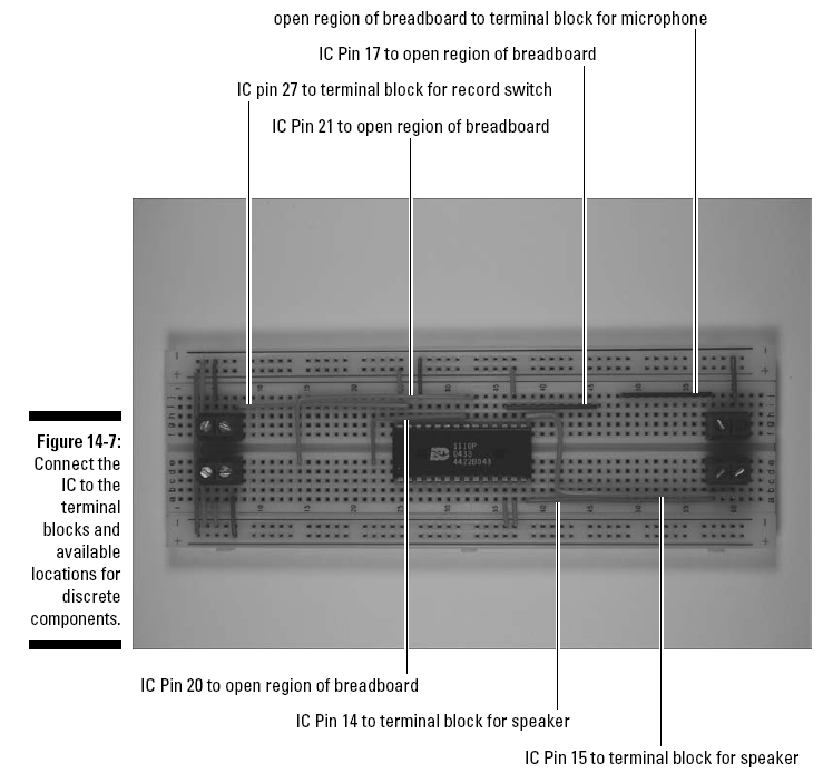
5. Insert discrete components and the tilt
sensor in the breadboard, as shown in Figure 14-8.
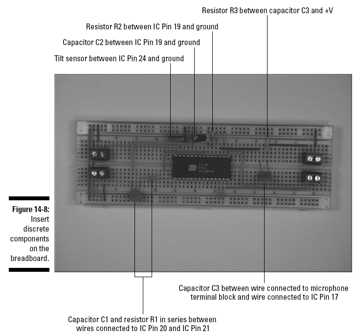
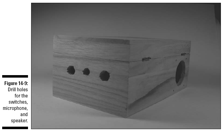
6. Drill holes in the Couch Pet-ato box for
inserting the switches, microphone, and speaker.
Figure 14-9 shows holes drilled in the front of
the box for the switches and microphone and the side of the box
for the speaker, but the placement is really up to you.
Whenever you drill holes or do any procedure
where bits can fly, such as clipping wires, wear safety glasses
to protect your eyes.
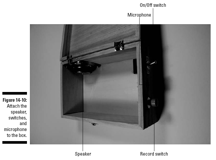
7. Attach the speaker, switches, and microphone
to the box, as shown in Figure 14-10.
We used
5⁄8"
6-32 screws and nuts to attach the speaker to the box. By
creating a very tight hole for the microphone, we could
press-fit it into the hole. (Press-fitting
means that you
don’t need glue or another method
to keep something in place.) The record switch was also
press-fitted into a hole although we did use just a drop of glue
to secure it. The on/off switch was
attached with the supplied nut.
8. Connect 6" wires (any color will work just
fine) to the speaker and the record switch and solder them, as
shown in Figure 14-11.
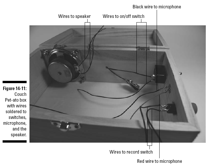
9. Connect the black wire from the battery pack
snap and another 6" black wire to the on/off switch and solder
them together, as shown in Figure 14-11.
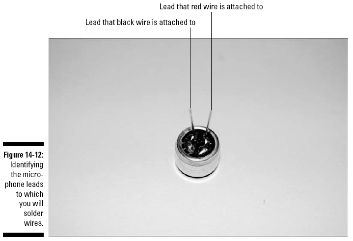
10. Connect a 12" red wire and a 12" black wire
to the microphone and solder them, as shown in Figure 14-11.
Figure 14-12 shows which lead of the microphone
you should solder the red and black wires to.
11. After the wires cool, wrap the solder joints
with electrical tape to prevent them from touching each other.
Don’t get sloppy now! Heed all the safety
precautions about soldering that we provide in Chapter 2. For
example, don’t leave your soldering iron on if you’re not
around. And for heaven sakes, don’t drop it in your lap when
it’s hot!
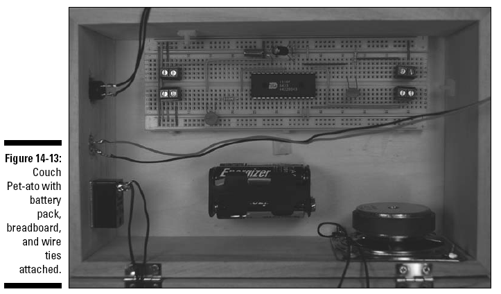
12. Attach Velcro to the battery pack,
breadboard, and box. Attach the battery pack and breadboard to
the box, as shown in Figure 14-13.
Note that we used three wire ties in the box to
secure the wires and keep them out of the way.
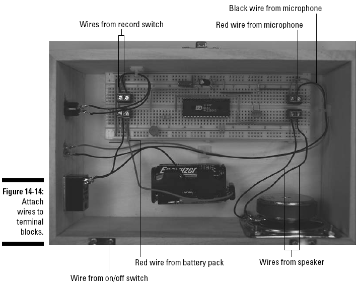
13. Attach the wires from the battery pack snap
connector, on/off switch, record switch, microphone, and speaker
to the terminal blocks, as shown in Figure 14-14.
When attaching the wires to the terminal blocks,
cut the wires to the length you need and strip the ends.
14. Close and latch the lid.
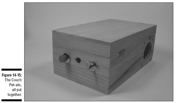
That’s it! The completed box is shown in Figure
14-15.