Scoping Out the Schematic
You have but one breadboard to pull together for
this project. Take a look at the schematic for the board in
Figure 14-2.
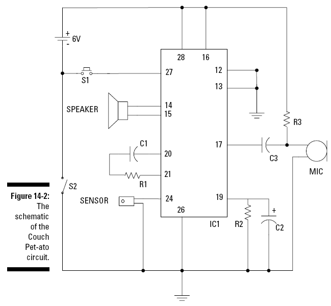
Here’s the rundown of the schematic elements:
The
sensor
— one of the key
components of this circuit — is used to
detect Fluffy jumping on the couch. This vibration/tilt
switch sensor detects motion or
vibrations when the switch is mounted with the body
of the sensor horizontal to the bottom of the box. When
the sensor detects motion, it closes a switch, just like how a
toggle switch works.
IC1 is the
other key component of this circuit. This is a chip that you
can use to record a sound or voice message and play it
back. We connected the sensor
between Pin 24 of IC1 and ground. When the sensor detects motion
and its contacts close, Pin 24 is connected to ground, which
triggers the playback.
S1 is a
normally open (NO) pushbutton switch that when depressed,
connects Pin 27 of IC1 to ground. This causes the IC to
record sounds or words that you
speak into the microphone. Recording stops when you
release the S1 pushbutton.
R3 is a
resistor that connects the microphone to the +V, supplying the
4.5 volts that the microphone needs to function.
C3 is a
capacitor that removes the DC voltage from the AC signal that’s
flowing from the microphone to Pin 17 of IC1.
The
speaker
is connected to
Pins 14 and 15 of IC1. The speaker is used
to play messages that you recorded on IC1 when the sensor
connects Pin 24 to ground.
S2 is the
on/off switch between the negative terminal of the battery pack
and the ground bus of the circuit board.
R1 and
C1
filter out electrical
noise.
R2 and
C2
connect the automatic gain
control circuit inside IC1 to ground.
The values of R2 and C2 determine how fast the
automatic gain control responds to changes in volume when you’re
recording a message.