Scoping Out the Schematic
This project is really easy. You have only one
breadboard to put together for this project. You can see the
schematic for the board in Figure 12-2.
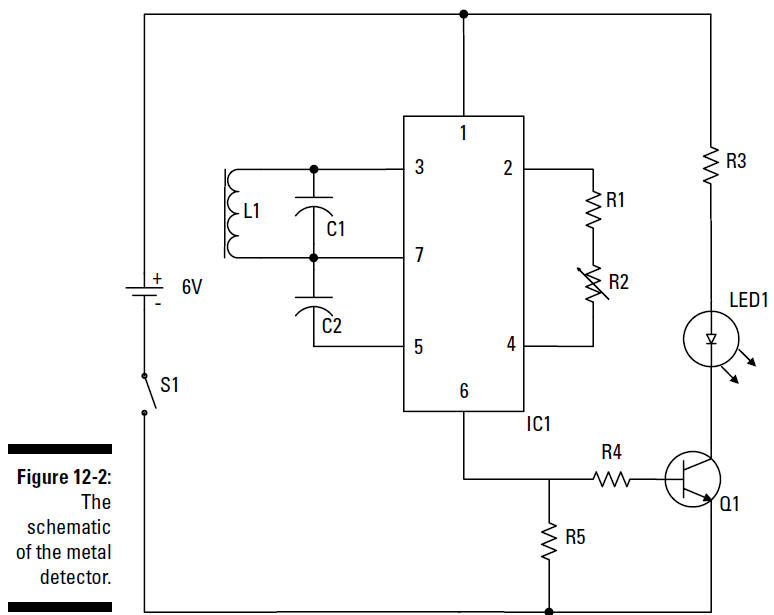
Here’s a list of the schematic elements:
L1 is a coil
(also called an
inductor)
wired in parallel to capacitor C1; the
combination of this dynamic duo is a parallel
LC
(inductor/capacitor)
circuit. When a signal that oscillates at several kHz
passes through this circuit, the
signal creates an electric field around the coil. When you
bring the coil near a metallic object, that electric
field induces an oscillating signal
in the object. Turnabout is fair play, so when the oscillating
signal has been induced in the metallic object, the
signal in the object creates an electric field that induces
current in the coil. This current
changes the oscillating signal running through the LC parallel
circuit.
IC1 is a
TDA0161 proximity detector. This IC is designed to supply the
oscillating signal that’s sent through the LC parallel
circuit. The IC also responds to
any changes in the signal: the IC has an output of 1 milliamp
(mA) or less if the coil is far from a metallic object
and an output of 10 mA or higher if the coil is near a metallic
object.
R1 is a
resistor, and R2
is a variable
resistor. These resistors are used to
calibrate the circuit in IC1 to the LC circuit. You
calibrate the circuit by adjusting
the value of the variable resistor when the coil is not near any
metal objects.
R5 is a
resistor connected between the output of IC1 and ground. When
the output of IC1 is on, current flows through this resistor and
provides a positive voltage to the
base of Q1.
Q1 is a 2N3904
transistor that you connect to the output of IC1. When
the output of IC1 is high, Q1 turns on and allows current
to flow through LED1.
LED1 is the
indicator light used to indicate that the device has detected
metal in the vicinity.
R3 is a
resistor that limits the amount of current flowing through LED1,
which prevents it from burning out.
S1
is the on/off
switch.