Building the box to house the circuit
The box that houses the circuit needs holes so
that you can place the LED, the potentiometer dial you use to
adjust resistance on the IC, and the on/off switch as well as
various wire connections.
Follow these steps to get the metal detector
circuit enclosure ready:
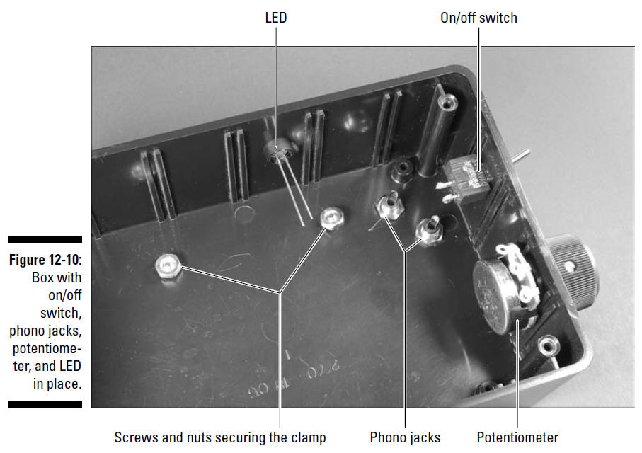
1. Drill holes in the box where you will mount
the LED, potentiometer, audio jacks, on/off switch, and clamp.
We put the on/off switch and the potentiometer
on one side of the box, the LED on one end, and the audio jacks
on the bottom. However, the placement is really up to you.
Figure 12-10 shows where we placed these components.
See Chapter 4 for more information about
choosing drill bit sizes for particular components and other
advice about how to customize a box for your projects. And guess
what? We always advise that you use safety glasses when
drilling.
2. Slip the threads of the phono jacks through
the drilled holes and secure with the nuts provided.
3. Slip the shaft of the on/off switch through
the drilled hole and secure with the nut provided.
4. Slip the shaft of the potentiometer through
the drilled hole and secure with the nut provided.
5. Slip the knob on the potentiometer shaft and
secure with the set screw.
6. Feed the top half of the LED socket through
the drilled hole from outside the box and insert the LED into
the top half of the socket from inside the box.
7. Slip the bottom half of the socket over the
leads and snap onto the top half of the socket to secure the
LED.
8. Solder the black wire from the battery pack
to one lug of the on/off switch and solder an 8" black wire to
the remaining lug of the on/off switch, as shown in Figure
12-11.
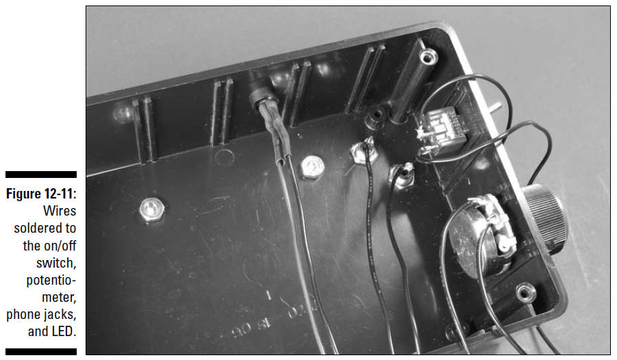
9. Solder an 8" wire to the center potentiometer
lug and another 8" wire to the left potentiometer lug, as shown
in Figure 12-11.
10. Solder a red 8" wire to the long lead of the
LED and a black 8" wire to the short lead of the LED, as shown
in Figure 12-11.
11. Slip a 1" piece of heat shrink tubing over
each solder joint and use a hair dryer to secure them in place.
12. Solder an 8" wire to the lug on each of the
phono jacks, as shown in Figure 12-11.
See Project Prep for advice about safe soldering
if you’re not very experienced in this art.
Putting it all together
After you have a box and a circuit, it’s time to
introduce them to each other.
Follow these steps to do so:
1. Attach Velcro to the breadboard and the box
and secure the breadboard in the box.
2. Attach Velcro to the battery pack and the box
and secure the battery pack in the box.
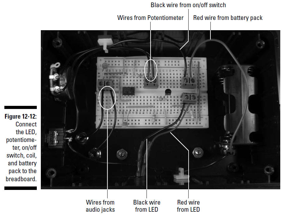
3. Insert the wires from the LED, potentiometer,
on/off switch, and battery pack to the terminal blocks on the
breadboard, as shown in Figure 12-12.
As you insert the wires, cut each of them to a
sufficient length to reach the assigned terminal block and strip
the insulation from the end of the wires.
4. Secure the wires with wire clips where
needed.
Handling the handle
To easily wander around pointing the metal
detector at suspected deposits of metal, you need a handle. Here
are the steps to do so:
1. Glue an 8", 1"-diameter PVC pipe into one end
of a 45°-angle PVC pipe fitting, facing up. (See the upcoming
Figure 12-13.)
2. Glue the other 45° PVC pipe fitting onto the
other end of the PVC pipe, facing down. (See the upcoming Figure
12-13.)
3. Glue a 3", 1"-diameter PVC pipe into the open
end of one of the 45° pipe fittings to form the coil end of the
metal detector.
4. Glue a 6", 1" PVC pipe into the open end of
the other 45° fitting.
This
becomes the handle end of the metal detector.
5. Glue the 1" PVC cap on the open end of the 6"
PVC pipe.
6. Drill a
3⁄8" hole in
the middle of the long section of PVC pipe on the side
that will be to your left when you’re holding the metal
detector.
You use this hole to feed the wires from the
microphone cartridge to the box containing your circuit.
Note:
If you’re left
handed, consider placing this hole
on the side that will be to your right when you’re holding the
detector so that you hold the handle in your left hand
and operate the switches with your right hand.
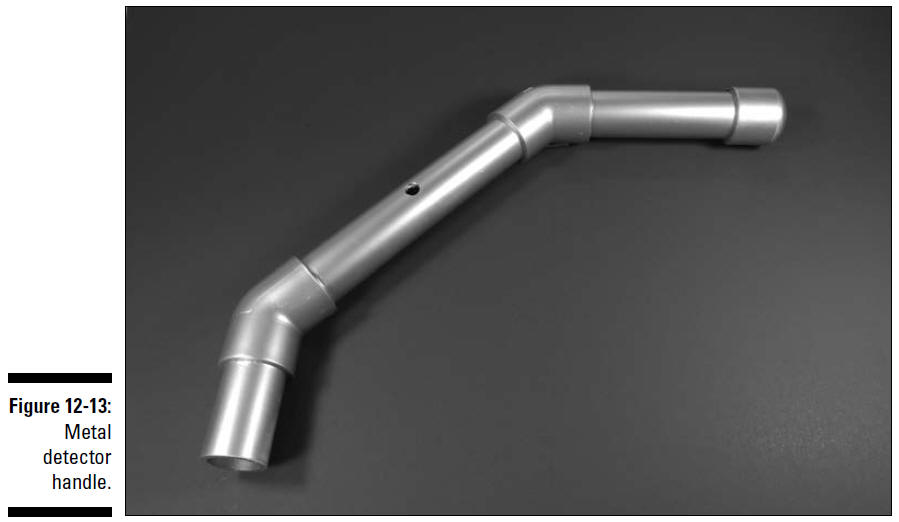
Figure 12-13 shows the PVC pipe and fittings
made into a handle for the metal detector.
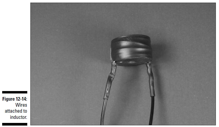
7. Solder 12" wires to each of the two inductor
leads, as shown in Figure 12-14. Slip a 1" segment of heat
shrink tubing over each solder joint and use a hair dryer to
secure the tubing in place.
8. Twist together the free ends of the wires
from the inductor and feed them through the PVC pipe from the
coil end until the end of the wire strand reaches the
3⁄8"
hole.
9. Form a hook shape with a piece of 20 or 22
gauge wire and pull the wires through the
3⁄8"
hole.
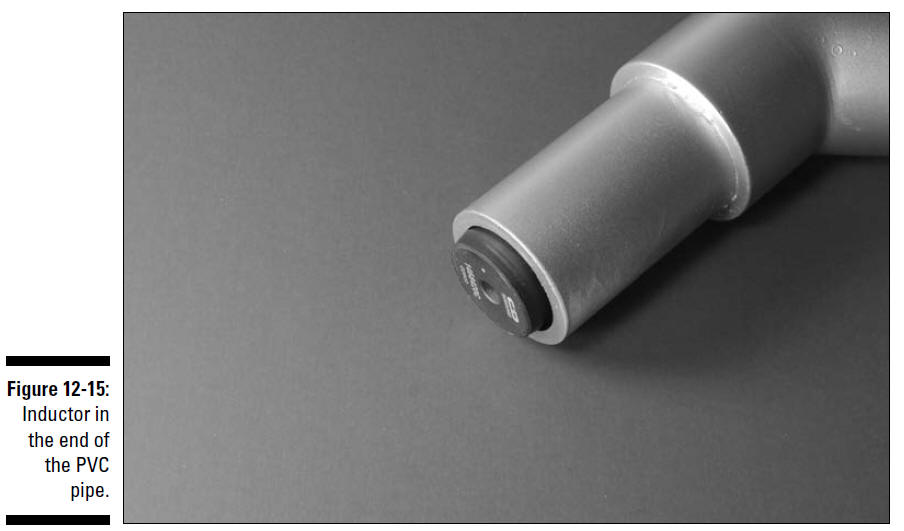
10. Insert the inductor in the end of the 1" PVC
pipe, as shown in Figure 12-15, and use some glue to secure the
inductor in the pipe.
11. Cut the wires to allow three inches to
extend from the
3⁄8"
hole in the pipe and attach each
wire to a right-angle phono plug, as shown in
Figure 12-16.
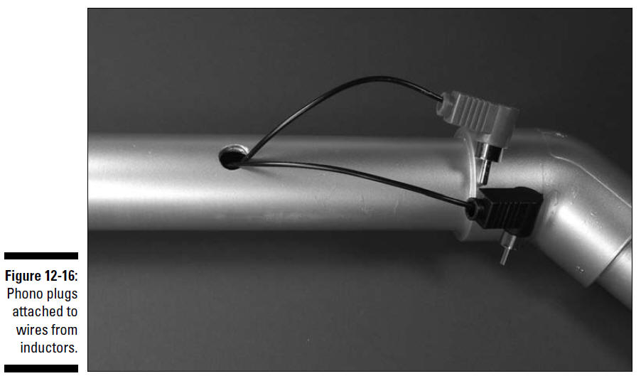
You can use either a plug that requires
soldering to the wire or one that uses a screw to secure the
wire, as we have here.
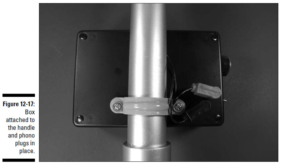
12. Press the clamp onto the 1" PVC pipe and
attach the box to the clamp with the 8-32 screws and nuts.
Figure 12-17 shows the box attached to the
handle.
13. Plug the right-angle phono plugs into the
phono jacks, as shown in Figure 12-17.
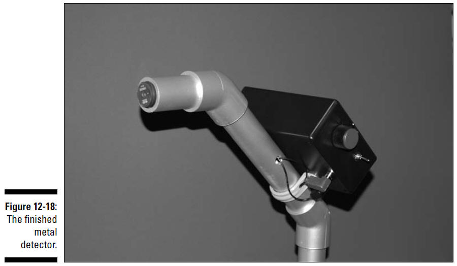
The finished metal detector is shown in Figure 12-18.