Building a metal detector circuit
The circuit in this project controls sending a
detector signal and processing the signal that comes back to
light up the LED. Here are the steps involved:
1. Place TDA0161 (IC1), 2N3904 (Q1), and four
terminal blocks (TB) on the breadboard, as shown in Figure 12-4.
The transistor pinout is shown in Figure 12-5.

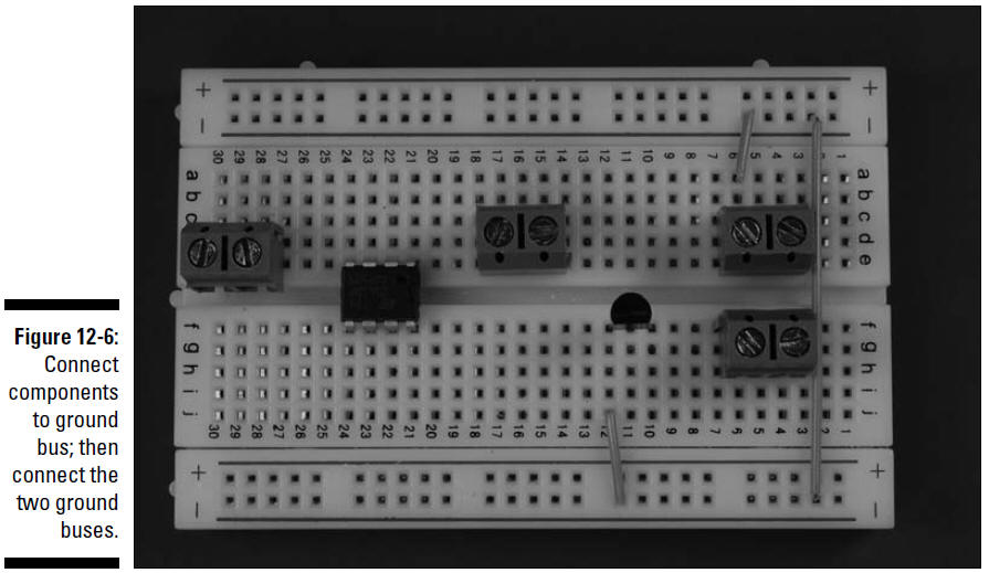
2. Insert wires to connect the battery terminal
block and the transistor emitter pin to the ground bus. Then
insert a wire between the two ground buses to connect them, as
shown in Figure 12-6.
Two shorter wires connect components to ground
bus; the long wire on the right connects the two ground buses.
3. Insert wires to connect IC1 and the battery
terminal block to the +V bus. Then insert a wire between the two
+V buses to connect them, as shown in Figure 12-7.

4. Insert wires to connect the IC and discrete
components, terminal block for the coil (L1), terminal block for
the potentiometer (R2), and terminal block for the LED, as shown
in Figure 12-8.

5. Insert two 0.0047 microfarad capacitors (C1
and C2), two 247 ohm resistors (R3 and R5), one 1 kohm resistor
(R1), and one 120 ohm resistor (R5) on the breadboard, as shown
in Figure 12-9.
We discuss in Chapter 4 how to determine how
short to clip the leads of many of these components to make them
fit neatly on the breadboard. Make sure you wear your safety
glasses when clipping leads!
