Let there be lights

All the brains of the circuit assembled in the previous section are there to make the Dance to the Music light display work. Here’s the part where you assemble those lights. Follow these steps to create your Dance to the Music display:

1. Select a series of musical notes, with eight high notes and eight low notes.

2. Draw a musical staff on the top of the wooden box in pencil and then draw a dot for the spot where each LED will go.

3. Drill test holes in a piece of scrap wood to determine the size of drill bit that you should use to give a press fit for the LEDs. We used a 13⁄64" drill bit.
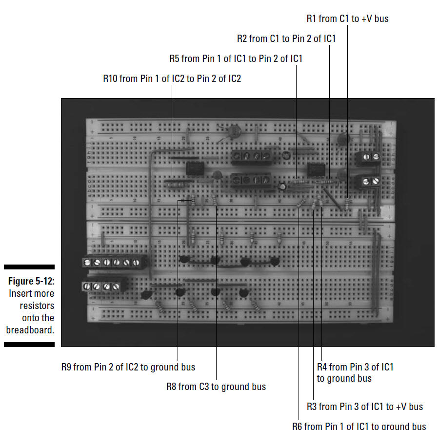
figure 5-12

4. Drill holes for the LEDs at the locations you marked in Step 3.

5. With a permanent marker or paint brush, draw the musical notes and staff on the wooden box.

6. Insert LEDs in the drilled holes. The box at this stage is shown in Figure 5-15.

See Figure 5-15 for help with this if you’re not musical!


R10 from Pin 1 of IC2 to Pin 2 of IC2

R5 from Pin 1 of IC1 to Pin 2 of IC1

R2 from C1 to Pin 2 of IC1

R1 from C1 to +V bus

R9 from Pin 2 of IC2 to ground bus

R8 from C3 to ground bus

R6 from Pin 1 of IC1 to ground bus

R3 from Pin 3 of IC1 to +V bus

R4 from Pin 3 of IC1 to ground bus

Figure 5-12: Insert more resistors onto the breadboard.

figure 5-13

7. Attach resistors between the pairs of LEDs, as shown in Figure 5-16. Attach the resistors to the short lead on one LED of each pair (four pair of each color) and to the long lead on the other LED of the pair.

8. Solder the resistors to the leads and clip the leads just above the solder joint. Clip only the leads to which you have soldered resistors. Figure 5-16 shows how the LEDs and resistors should look at this point. Figure 5-17 shows a close up to help you see the soldering more clearly.

figure 5-14/5-15

figures5-16/5-17

Be sure to heed all the safety precautions about soldering that we provide in Chapter 2. For example, don’t leave your soldering iron on if you have to step away to let the pizza delivery guy in. And just in case a bit of solder has an air pocket that could cause it to pop, wear your safety glasses whenever you solder or clip leads and wires.

9. Connect and solder short lengths of 20 gauge red wire between the remaining long LED leads. Then attach a 12" 20 gauge red wire to the remaining long lead of the first LED pair, as shown in Figure 5-18. These wires are the +V bus for the LED arrays; you attach the 12" wire to a terminal block to supply voltage to the bus.

figure 5-18

10. Clip the LED leads just above the solder joint. Clip only the leads to which you have soldered the red wires; you need the remaining leads in the next step.

11. Connect and solder a 12" 20 gauge black wire to the remaining short LED lead on each pair of LEDs, as shown in Figure 5-19.

figure 5-19

You will connect each of these eight wires to a terminal block. The upcoming Figure 5-20 shows these connections close up.

figure 5-20

12. Clip the LED leads just above the solder joint. Make sure that the LED leads and solder joints don’t touch each other. Coat them with liquid electrical tape to help prevent any shorts that could occur if you bend or push the wires together.