Building a circuit
Time to go one-on-one with your
breadboard. Grab your schematic, tape it to the wall, and get going.
Electrolytic capacitor Potentiometer Ceramic capacitor Transistors
Terminal block Electret microphone Op amp On/off switch LED Resistor
Here are the steps involved in building the circuit:
1. Place the two LM385 ICs (IC1
and IC2) and 11 terminal blocks on the breadboard, as shown in Figure
5-4.
As
you can see in this figure, each terminal block has connections for two
wires. Here’s what the wires get from each block will be connected to:
• Wires from one of the terminal blocks on the
right side of the figure go to the battery pack.
• Wires from the other terminal
block on the right go to the microphone.
• Wires from the terminal blocks in the center go to
the potentiometers.
• Wires from the terminal blocks on the left side of
the breadboard go to the LEDs.
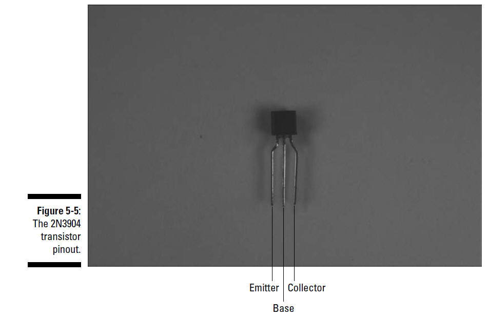
2. Place the eight 2N3904 (Q1–Q8) transistors on the
breadboard, as shown in Figure 5-4.
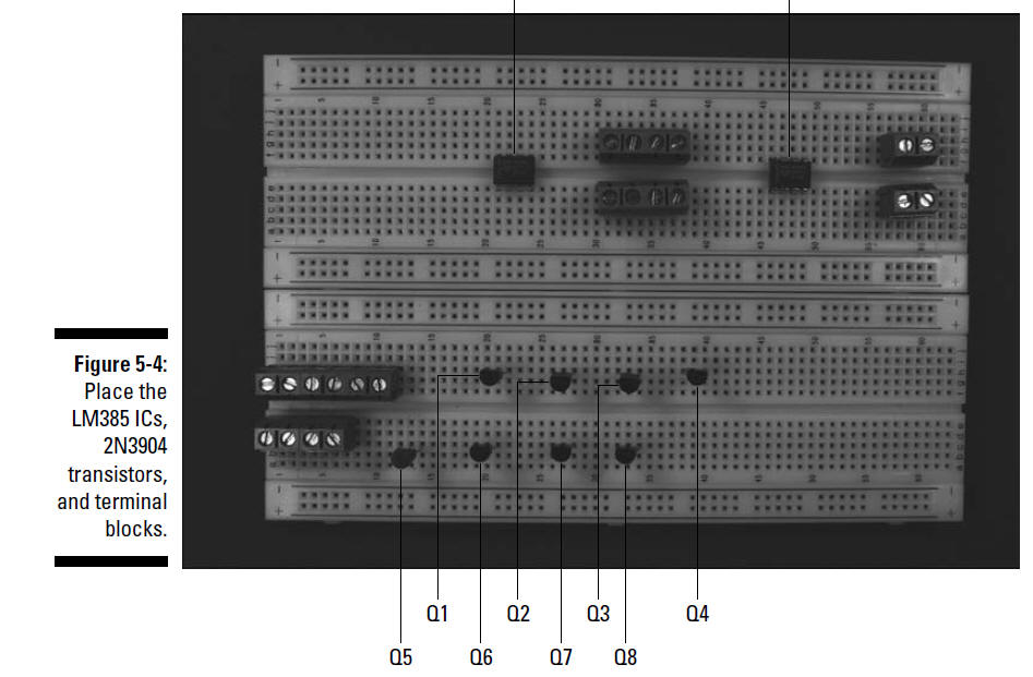
Insert each transistor lead into a separate
breadboard row with the collector lead to the left side (as shown in
Figure 5-4), the base lead in the center, and the emitter lead to the
right. The pin designations of the 2N3904 transistors are shown in
Figure 5-5.
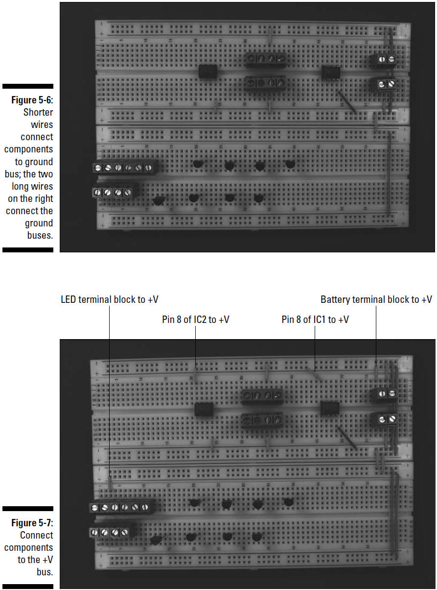
3. Insert wires to connect the
ICs, the battery pack terminal block, the microphone terminal block, and
the potentiometer terminal blocks to the ground bus. Then insert wires
between the ground buses to connect them to each other, as shown in
Figure 5-6.
The ground buses are designated by a negative (–) sign on this
breadboard.
4. Insert wires to connect the
ICs, the battery terminal block, and one of the LED terminal blocks to
the +V bus. Then insert wires between the +V buses to connect them, as
shown in Figure 5-7.
The +V buses are designated by a + sign on this breadboard.
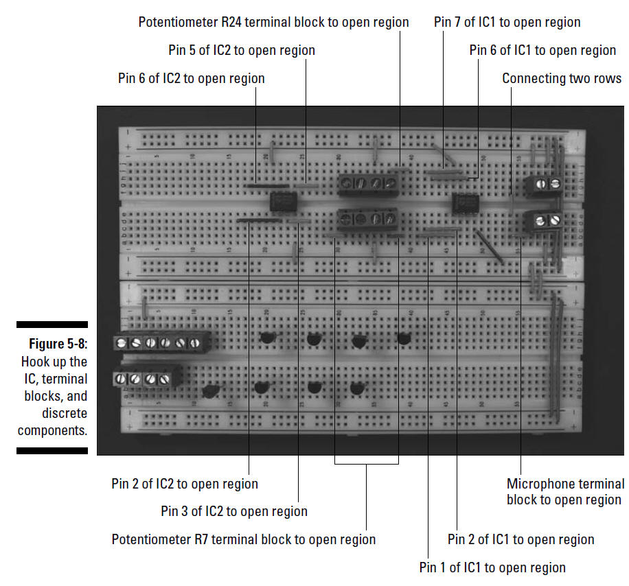
5. Insert wires to connect the ICs, terminal blocks,
and discrete components, as shown in Figure 5-8.
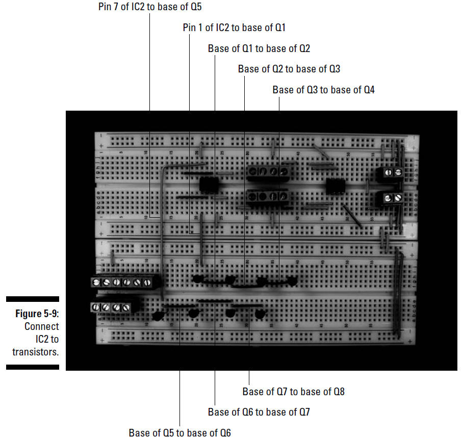
6. Insert wires to connect IC2 to the transistors and
the base pins of the transistors to each other, as shown in Figure 5-9.
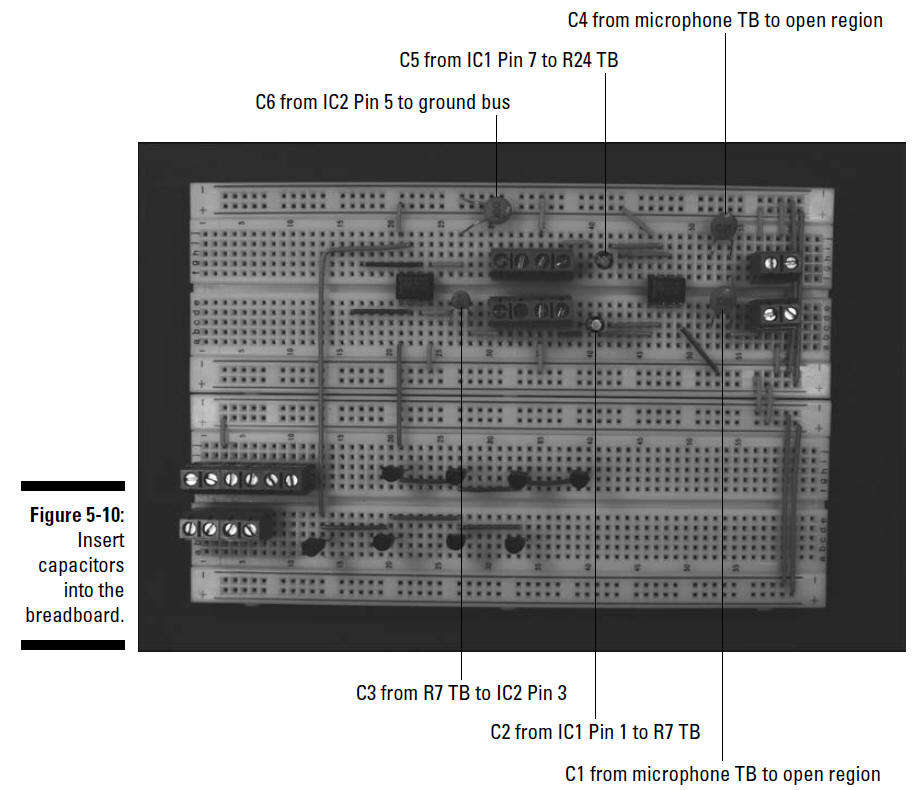
7. Insert three 0.1 microfarad capacitors (C1, C4,
and C6), two 10 microfarad capacitors (C2 and C5), and one 0.001
microfarad capacitor (C3) on the breadboard, as shown in Figure 5-10.
Use both the schematic and the photo to place each component. For
example, the schematic shows that the + side of C2 is connected to Pin 1
of IC1 and that the other side of C2 is connected to potentiometer R7,
so insert the long lead of C2 in the same row as the wire connected to
pin 1 of IC1 and the short lead in the same row as the wire connected to
the terminal block for potentiometer R7.
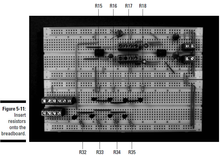
8. Insert eight 1 kohm resistors (R15–R18, R32–R35)
from the emitter pins of each transistor to the ground bus, as shown in
Figure 5-11.
9. Insert one 2.2 kohm resistor (R1), one 2 kohm
resistor (R2), two 47 kohm resistors (R3 and R4), one 100 kohm resistor
(R5), two 5 kohm resistors (R6 and R8), one 1 kohm resistor (R9), one 5
kohm resistor (R6), and one 220 kohm resistor (R10) on the breadboard,
as shown in Figure 5-12.
10. Insert one 2 kohm resistor (R19), two 47 kohm
resistors (R20 and R21), one 100 kohm resistor (R22), one 5 kohm
resistors (R21), two 1 kohm resistors (R25 and R26), and one 220 kohm
resistor (R27) on the breadboard, as shown in Figure 5-13.
11. Insert wires to connect the collector pins of the
transistors to the terminal blocks, as shown in Figure 5-14.